
Title:Intelligent Emergency Assistance for Vehicle Operator
Displayed Name:Deepakkumar Ravichandran
| Concept / Overview |
|---|
| In this project we are focusing the vehicle operator's heart rate monitoring while the vehicle is in motion then alert the operator for the precaution activities. If the operator heart rate is in critical condition and unconscious too then the operator lost vehicle control, by receiving information from the heart rate sensors the vehicle will be gradually parks at the road side of an highways or in City in heavy traffic with the help of intelligent system i.e. GR peach board with IOT. Then the emergency systems will be executed, the send information to nearby Hospital through IOT. |
Introduction
Heart attack is a disease in which proper and continuous
Care should be taken. During the last two decades heart rate monitors have become a widely used in various applications such as medical, sports etc .The development of new heart rate monitors are also evolved rapidly during the last twenty years and the research focused more on heart rate monitoring. In which 24 hours of patient’s monitoring is necessary.
While the vehicle is in motion if operator may attack some heart problem in that condition the person who driving the vehicle he may lost the control of the vehicle. So, we have worked on this system which will be used when operator driving a vehicle continuously monitoring the operator heart beat through pulse using sensors. When system identifies pulse rate is not normal then auto warning message will be placed in display. If continuously pulse rate in abnormal condition then emergency mode will be activated.
In Emergency mode vehicle will slow down and park automatically at road side without disturbing the other vehicles on the Road and Safety indication will be switch on the vehicle. After which the information is send to nearby Hospitals.
Sound Horn and Indicators glow in order to attract the attention of other vehicle operator.
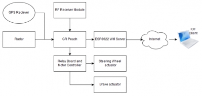
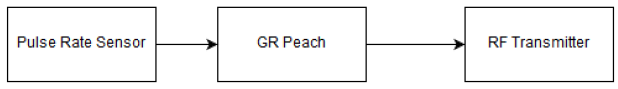
Block Diagram
Hear Rate Detector Block
Driver Assistance Block
Pulse Rate Monitoring
The Pulse rate monitor consists of:
- Pulse Rate Sensor
- Renesas GR Peach
- RF Transmitter
Pulse Rate Sensor:
The Pulse Rate Sensor will sense the pulse rate gives out the voltage ranging from 0 to 3.3 v
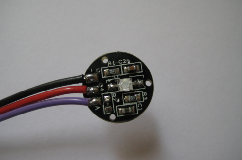
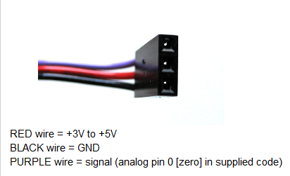
The Analog Voltage id given to A0 pin of GR Peach and Converted in 0 to 1 voltage range.
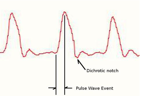
The Above Picture is the pulse sensor output. Only the dichrotic notch in the waveform is traced. The highest voltage in the waveform corresponds to dichrotic notch and number of dichrotic notch per min is the pulse rate. The pulse is calculated by the Renesas GR Peach Board and stored when the pulse rate is abnormal then usual pulse and the spike of voltage or dip of voltage occur in the waveform occurs. Which is detected by Br peach and a Pulse is triggered by the RF Transmitter module. Which is show in the image below:
Refer the link for the flow chart of the process.
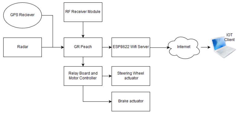
Driver assistance block Explanation
The Driver Assistance Block Consists of:
- Ultra sound transmitter and receiver module(HC-SR04)
- Two channel Relay Board
- Braking actuator
- Steering actuator
- RF Transmitter
- ESP8266 WIFI module
- PC with Socktester client
- GPS Receiver.
The Ultrasound Transceiver module is placed at front of the car which act as a RADAR to the Model. I have used Remote control car as my prototype .the front motor is steering motor and Rear Motor is called Driving Motor. It is assumed that rear motor as Engine and Front motor as steering. When the Brake need to be applied. The both the input of the L293 Motor driver are set High or Low and thus the Motor come to stop and Steering motor is locked when the High or Low value is applied to the input f L293 Drivers.
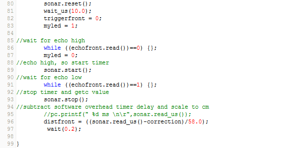
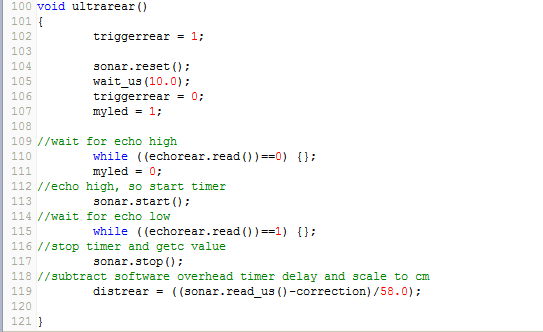
The ultra sound sensor is placed at the front and it has one transmitter and receiver. The picture is shown below.
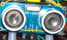
Vcc is connected to %v and Trigger and Echo are connected to the Gpio GR Peach. The Trigger is made high and trigger pulse is generated and when the receiver get back the echo the Echo pin is mode High.
Distance between the obstacle and the Car can be detected easily with this module.
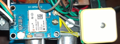
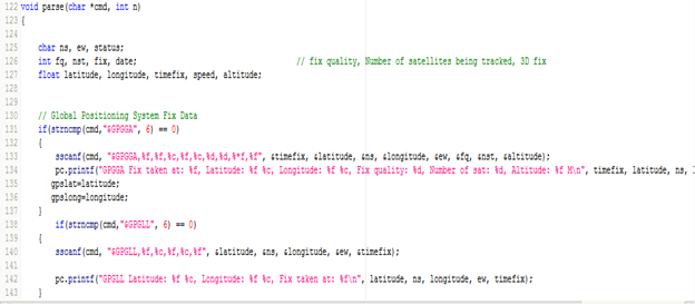
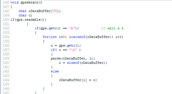
The GPS Receiver is GY-GPS6MV2. The continuously sends the location is following format as showing the image below.
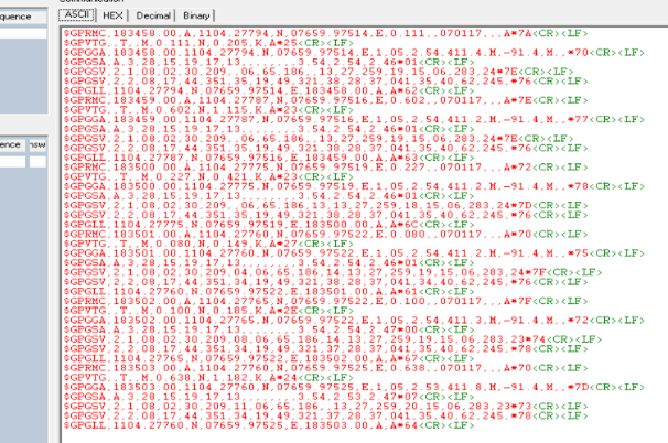
The Picture of the GPS Receiver is shown below.
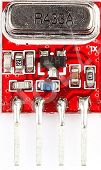
The RF Receiver is shown in the image below.
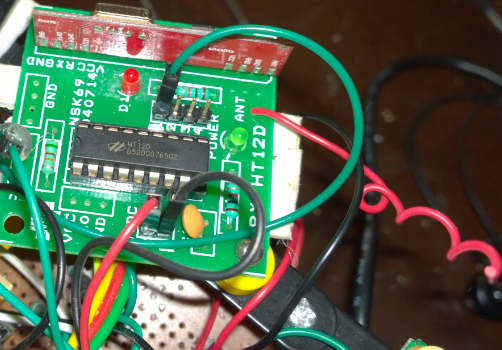
RF Receiver has 4 Bit Data output. I this project I am using only one Bit as signal to GPIO of Renesas Gr Peach.
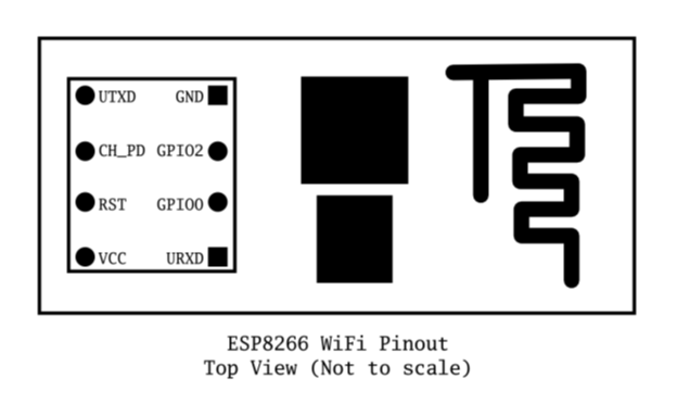
The Esp8622 WIFI Transceiver is configured as server and Socktester application is used as a client.
The picture of the ESP8622Module is shown in the below image.
Working
When the hand held Pulse rate monitor sense a critical situation for the Driver a signal I transmitted through the receiver. When the Driver assistance receives the signal it quickly sense the environment and act according the algorithm in the flow chart.And hence the vehicle comes to a stop and Gps Location is sent to a IOT Device installed in nearby hospital.
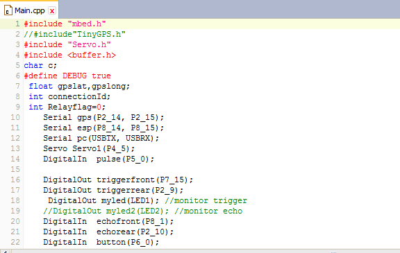
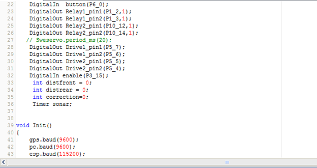
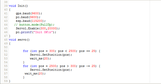
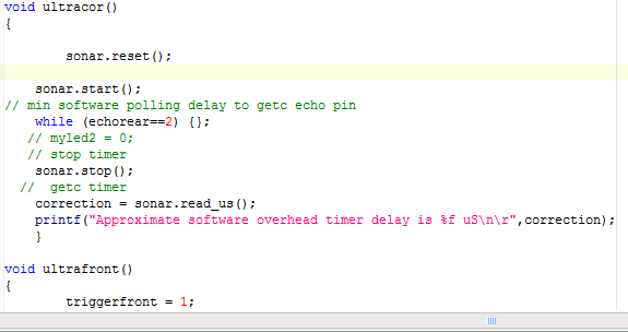
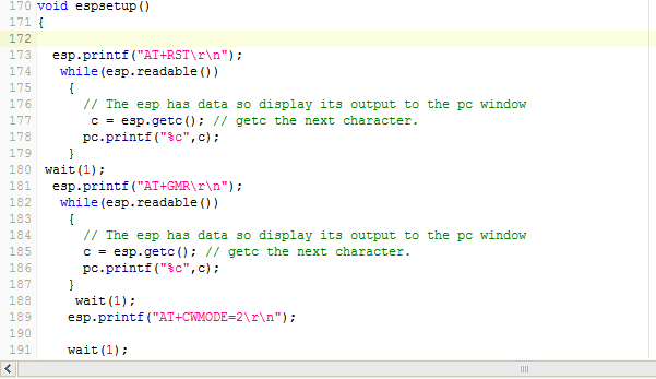
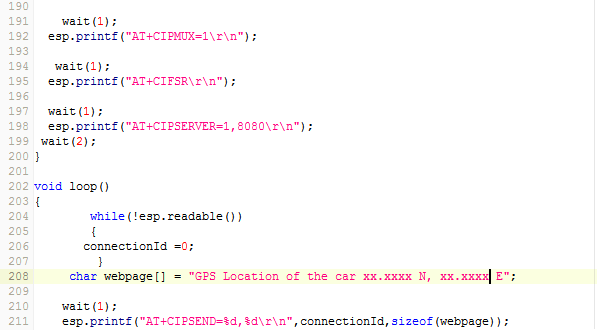
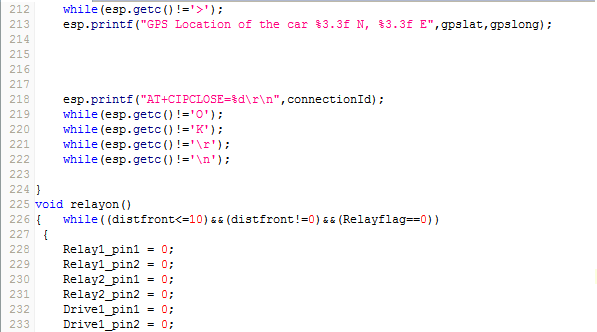
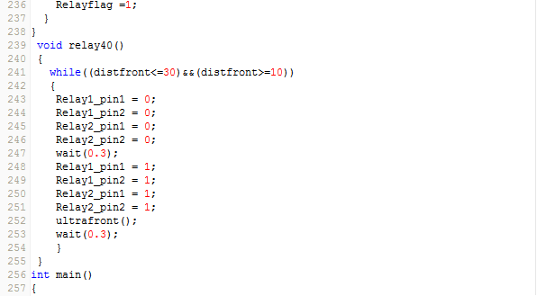
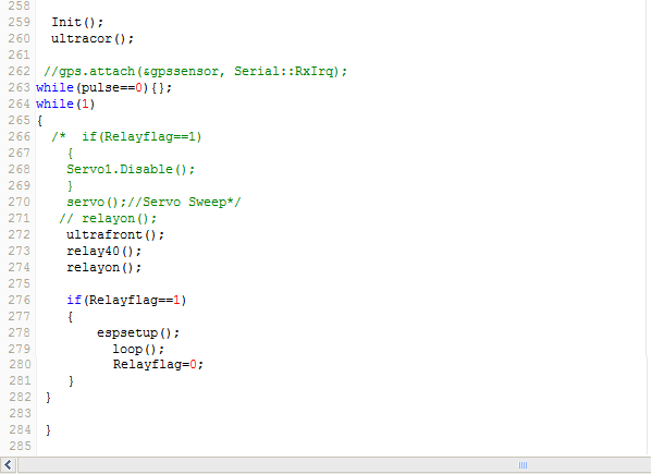
Source Code
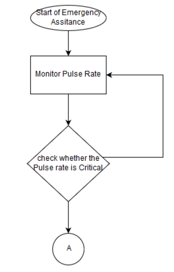
Flow Chart
Heart Rate Monitor
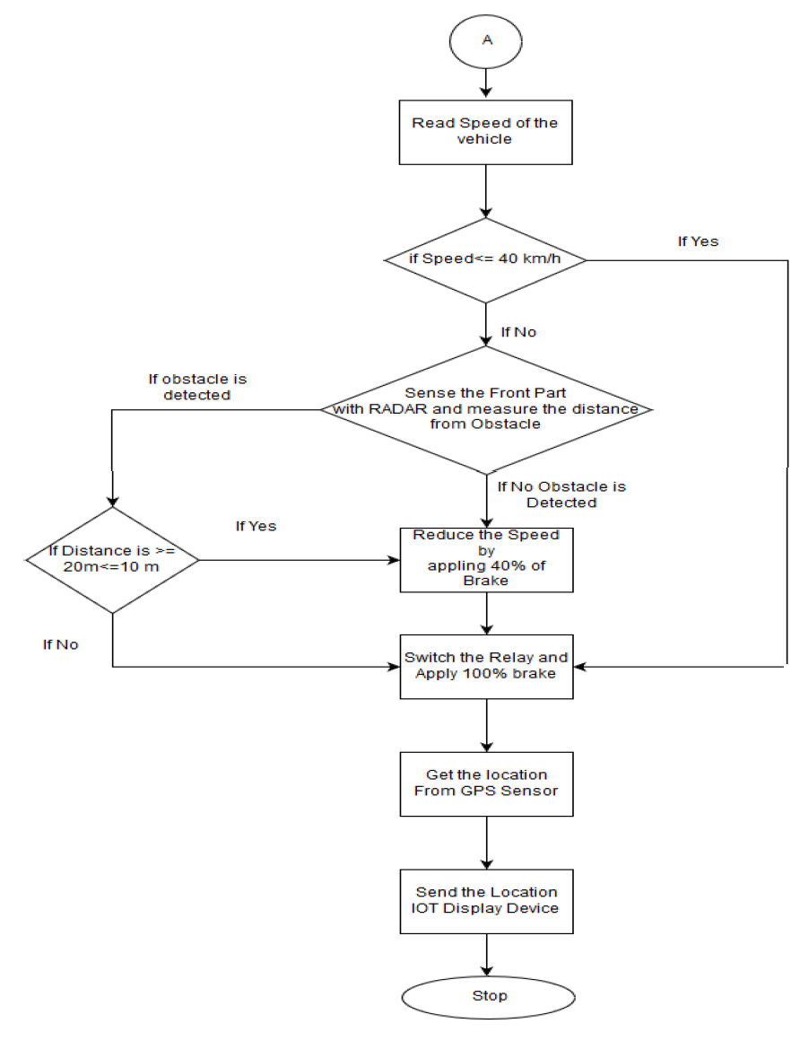
Driver Assistance Flow Diagram:
Conclusion and Future
In Future the vehicle automatically cruise to the hospital. With helped Camera and RADAR.
Finalist on GR-PEACH design contest in India 2016
