Title:Mini gateway for automation and security
Displayed Name:NEO Innovations, Hyderabad
| Concept / Overview |
|---|
| A mini gateway for Commercial & Security Automation with high processing power to compute most of work required. Also includes a inter communication with other gateways to form a peach network. |
Abstract
To design a gateway for low power wireless communication which has a broader usage, user friendly navigation and easily available to be controlled from the network with real time pictures and processing available directly from the gateway or over the network based on requirements of it end usage.
Block Diagram
Initial Design Idea
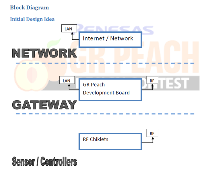
Gateway Design
The initial gateway design presented in the abstract has been modified as per requirements while designing. The block diagram gives a general view of the system which be explained later in the description.

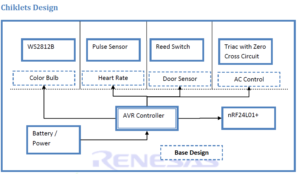
Chiklets Design
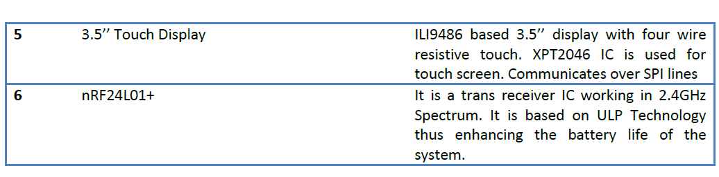
Specifications
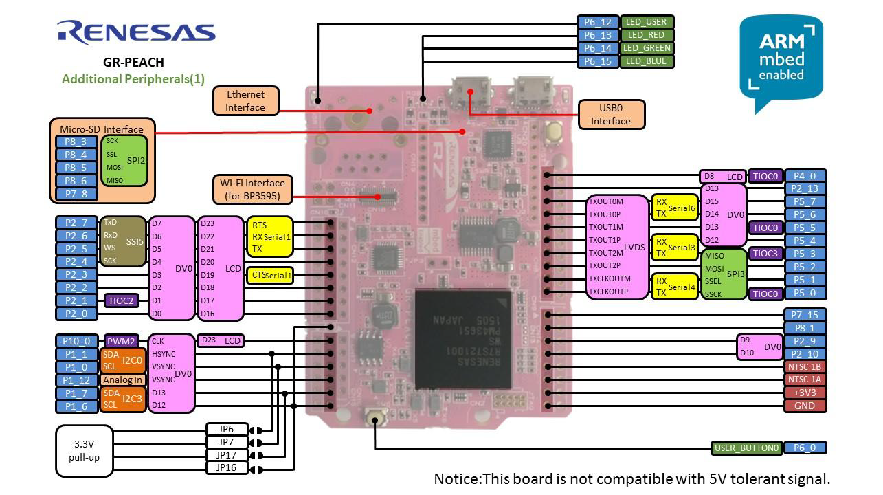
GR Peach Development board
The heart of the project i.e. Peach development board consists of Renesas RZ / A1H Cortex A9 Processor with speed up to 400MHz and 10MB RAM. High number of peripherals and support of mBED makes it a highly advanced and ready to go platform for developing Embedded System Applications.
Chiklets
The Chiklets are basically powered by AVR Controllers for the ease of programming of Arduino. They have a very simple base block diagram. The AVR Controls the Radio module using SPI. It is either powered by the battery or using AC to DC Converter.
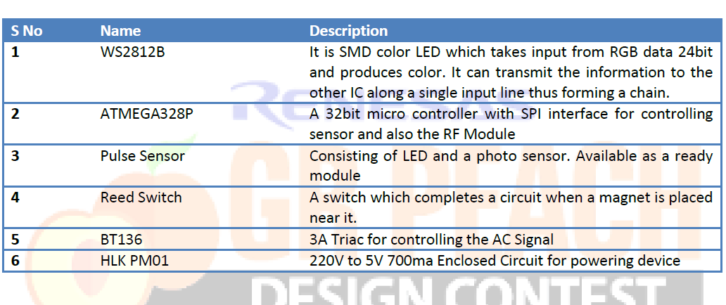
All the major components that have been used for making Chiklets have been discussed. Circuits are mostly open source and can easily be available or re created using Arduino. The IC i.e. ATMEGA328P is Arduino Boot loaded controller only.
Estimated Cost of Additional Components
Since most of the components were present alongside project and few were purchased, the rough estimate for designing the project (except peach) would be around Rs 10000/- to Rs 11000/- which include the casing of the system.
Hardware design
Description
As seen in the above block diagram of the gateway, the peach has to control the various modules connected to it, also needs to take input from the network and touch screen and produce relevant output in both the networks. Let us go through the hardware description where the diagram will tell us how peach is connected to various modules or vice versa.
Hardware Design
Since various modules are connected to the GR Peach development a central circuit diagram would be difficult to be shown directly. Thus here we describe each module and its connection to peach with pin names supported by mBED.
GR Peach (Reference Design from mBED)
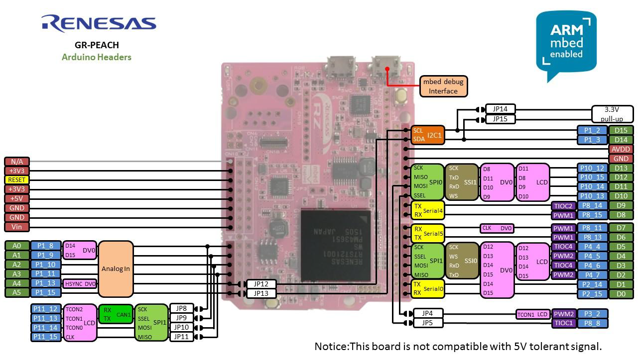
The entire software is built around mBED platform and libraries from mBED have been used. All connections are from the mBED reference design. Now a brief description about the hardware and its connection to the Peach is given below
3.5’’ Touch LCD
The ILI9486 TFT LCD Module consists of total 26 pins. This LCD is mostly used as a Low cost variant for raspberry pi display.
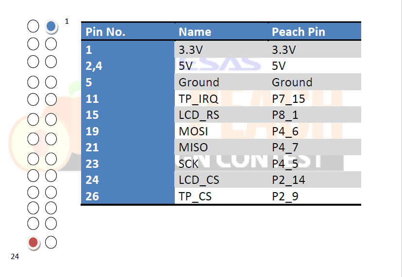
The 3.5’’ Touch LCD consists of ILI9486 based 480 X 320 Controller and XPT2046 based touch controller. The SPI lines of touch controller and display controller are combined leaving the CS of each independent. However for LCD only writing option is available. The max SPI speed of this LCD is 20MHZ (based of min 50ns for write option).
It has a inbuilt memory RAM to which we can write information. However by utilizing peach ram a replica of the system is kept inside the peach itself for faster operation.
nRF24L01+ RF Transceiver Module
The nRF24L01+ module is based GFSK modulation of 2.4GHZ spectrum. It can communicate with 6 more modules with its 20bit addressing system. It can go into low Sleep power modes and Can take max of 13mA. Thus it can be greatly used for Low power devices.
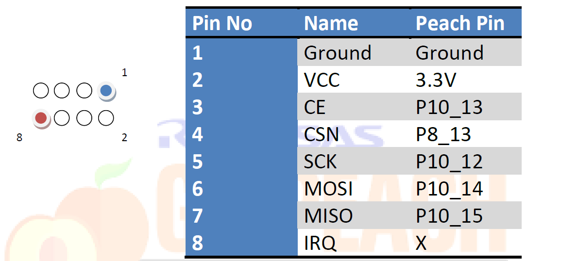
The nRF24L01+ communicates over the SPI Lines. It can work only in one mode at a time. That is either is receive or transmit mode. It consists of 30 bytes buffer and transfer with the address set in Tx address. It can receive from 6 different modules. However there first four bytes need to remain same. It power supply pin usually varies. So it needs to be decoupled with a capacitor of around 10uF.
PAL Camera
The PAL camera consists of just three pins as below.
1. 5V
2. Signal (NTSC 1A)
3. Ground
The signal pin is connected to peach NTSC 1A and the information is resent in the form PAL signal.
LM35 Temperature Sensor
The LM35 also consists of three pins and it produces analog signal equivalent to temperature in the surrounding.
1. 5v
2. Signal (A4 pin of peach)
3. Ground
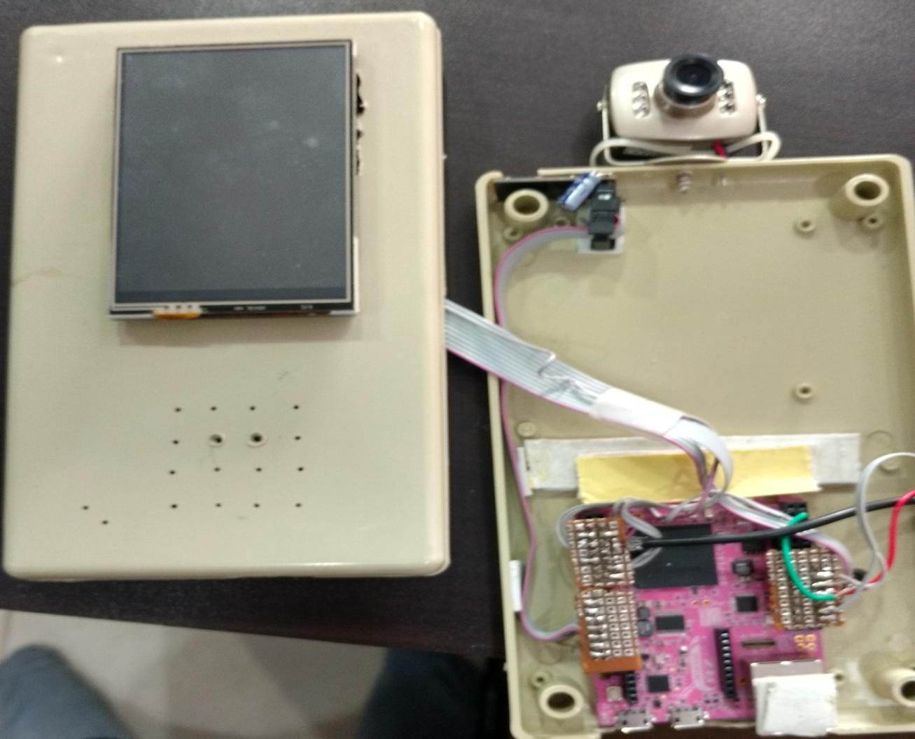
The LM35 is a precision temperature sensor producing output equivalent to the temperature of the surrounding. It has around 0.1®C This completes the hardware section of the Mini Gateway. We also have an SD Card which is directly connected to peach on SPI2 interface. The connection were made using FRC cable and then placed inside a Box. The reset pin was also connected outside for ease of programming. A picture of the entire module is shown below

Software design
The software was designed in three different environments one for each i.e. the GR Peach (mBED Platform), Chiklets(Arduino), Smartphone (Android Studio). The other two platform code wouldn’t be explained here as they can easily be produced in any environment. However the entire source code is uploaded.
Lot of code has been written behind, with lot of changes to libraries available to be used with peach board. The video explains the entire working of the project. Here, we discuss the internal working of the program designed.
A basic flow chart depicting the system is mentioned below.
Initial conditions
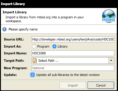
Since the images use RAM space for storing images alongside program, initial changes were made to the .sct file for increasing the space. MBED-dev folder can be referred for these changes. Most libraries which were imported for the project have uncommitted changes since the settings can only work on peach due to its speed and RAM. For example lot of changes have been made to Unigraphic library for it to work correctly with peach and ILI9486 controller.
Graphical User Interface (GUI)
Plenty of RAM is available when it comes to creating a rich user interface for the end user. However due to lack of speed from the ILI9486 controller the refresh rate is around 2Hz which may cause a lack of viewing. But low cost of the screen used gives a solid back support as this screen is only used in case of no network device is available or in case of emergency.
Firstly, the editing of the pictures is done with open source GIMP software. The screen supports RGB565 format and thus the pictures are stored in BMP with the same format. All the pictures are initial present in the SD card. When the screen is initialized for first time, the pictures are bought into RAM memory and thus the process of Virtual Memory is created which can easily be used between RAM and SD Card for storage.
Since a four wire resistive touch is employed for input from the user, the screen is divided into windows where only that part of screen is changed based on the user input. And since the menus are stored in RAM of peach, one cannot see a really lag between touch input and display.
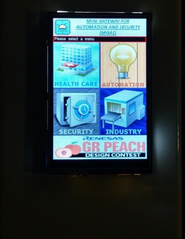
A total of four categories in menu form are shown to the user. Here we describe them in detail in next sections.
The four categories are
1. Health Care
2. Automation
3. Security
4. Industry
Before starting the explanation of the above four categories, a discussion on the RF Module and its code is specified below.
RF Trans Receiver (nRF24L01+)
The RF Module used in the system has built in complete circuit for transmitting information over the 2.4GHz spectrum. Based on its GFSK Modulation, it has more than 100 channels with the band gap of 1 to 2MHz. It is can be switched between RX and TX mode based upon the command.
In this system this module receives or sends information to the sensor or the controllers in the form of packets. The packet format is rudimentary as of now and was designed to support the present controllers that are in Chiklets. These RF Controllers can receive data simultaneously from six different modules under some conditions. So we can create a RF Network from them.
The Peach basically after initializing the system waits to receive some content from the RF Network. Once data is received it is decoded and then shown to user on the Screen. In the same way if the user wants to send some information, he selects the relevant button from the screen which is then encoded and sent to the Chiklets. So here the RF module plays an important role in creating the RF network.
Health Care Menu
It displays two things. One is present inside the box itself and gives the temperature that is inside the box. LM35 is connected to one of the analog pins of the peach which is converted into digital and then to centigrade. The other information is the heart beat. It comes from the heart beat Chiklet.
As the module of heart rate is switched on, the sensor starts detecting the beats of the person, when he keeps his finger on the sensor. This is calculated into BPM and stored in a variable. Then after every one second, the BPM is converted into a packet and sent over RF to the peach, which receives it and displays it over the screen.
Automation Menu
In this a color information is sent over the RF to the Color Bulb to display a specific color. The screen consists of various colors. When the user selects a color, the color is then converted into a packet with RGB values of 8 bit each and then sent over the RF network to the color Bulb.
The color bulb consist of 5 LED’s of WS2812B which takes the information about the color received and then pass the decoded 24bit color information to the led which in turn display the color. Any color can be selected from the menu displayed on the screen.
Security
It has a picture of door closed and an option for the camera. This screen actually shows the status of the door sensor Chiklet. The door sensor Chiklet consists of a reed switch which on coming close to a magnet turns on.
When the door is opened the magnet goes far off and the reed switch opens. This information produces an interrupt which wakes the system from sleep and then sends a packet over the RF to the Peach board. A door opened picture is then shown on the screen. This is completely powered by two AA batteries and has a great range. It will go into sleep after the interrupt thus saving power.
A camera option is available for user selection. When the user selects the camera option, whenever the door is opened a picture of the person opening the door is taken. A lot of information is processed in the back ground with the flow shown below.
From the above flow chart it is clear that the picture is captured in YCBCR422 format and needs to convert to RGB565 format for LCD display. However due to its processing speed, almost no lag is seen in displaying the image and converting it into JPG.
Industry Menu
The industry menu is used to control the AC signal present on a remote device. Basically the industry Chiklet consists of a Triac circuit which is controlled by an AVR. Based on the cutting of the AC signal, the intensity of the bulb is controlled.
Instead of the bulb we can even place a motor or a blower and control it speed. In the menu, the user selects either to switch on or off the bulb or he can increase or decrease the intensity by using the plus and minus button. Even the intensity is shown on the screen with which the bulb is glowing.
Thus we can see how peach is able to control or get information from sensors and process and display the information on the LCD screen. This is done smoothly with almost no lag. Thus real time processing can also be done for medical systems using peach and if required in depth data analysis on the input can be done in parallel.
This is where the peach RF Network comes into play. However now we have to use the Peach Ethernet for transferring the information on the other side that is either internet or cloud. Next section discusses them.
Peach Servers
Peach has already enabled the RF Network, now it times to start communicating over the most common interface that is the internet. Here for this the peach is connected using Ethernet cable to a wireless network bridge. The Ethernet library of mBED has been used to communicate over the internet.
Now there are two servers actually running on the peach. One is used to communicate with the android app on the mobile and the other is the http server. So basically to say the first once can be used like an MQTT Client or like an application server. The later would anyway support the web server model.
So the android app is basically a client and the peach act as a server. When the app connects to the server, the loop starts receiving any information that is sent from mobile. Reversely any information received from the RF network is sent over the Wi-Fi network to the android app. Thus here peach act as a gateway between RF Network and Wi-Fi network.
The http server is used to display the image that is stored on the SD card over the internet. The image can be seen by opening a browser and entering the URL of the Peach module. The IP Address has been fixed for the module.
Both the servers are polled inside the loop function and are frequently accepting a client for connection. As of now only one app can connect at a time to peach.
Android App
The Android App was designed in Android Studio. It is a simple client server model with a GUI for sending or receiving information. However a mobile app basically follows messaging protocol like MQTT. This requires a MQTT Broker and an MQTT client for Peach and Android.
Conclusion
The prototype clear shows how peach can stand apart in creating a perfect Gateway. However the name is basically a mini gateway. Why So? Let’s go back to the block diagram. A camera is present.
A basic scenario of a security system in a Commercial establishment consists of security cameras. They basically capture images and send them to a DVR. Today they have modernised to IP Cameras. They send information through Wi-Fi to the server. Well the peach also has a camera interface that also two parallel cameras can be connected together. So if the Video Camera streaming over IP is actually a peach which also can form an RF Network thus making a gateway and an IP Camera. This configuration is enabled in every IP Camera. These cameras can also talk to each other over the network.
For example a mini peach camera takes the information about a door opened from it RF Network and then communicates to all the other mini peach cameras to start their respective recording and also switch on lights of their rooms. This is the main idea behind the project which makes it a low cost mini gateway.
Future Implementation
RTSP protocol implementation on peach for live video streaming over IP. This is the first important thing to be implemented. Development of messaging protocol for transferring RF Network information over the LAN and other cloud based system.
RTOS implementation and encryption would be other important things both in the RF Network and on the cloud.
Demo Video
Project Links
Due to space constraints and memory, the files where uploaded to the following link.
https://drive.google.com/drive/folders/0Bz0BkcDlflbiM1hDUUhYaFFranc?usp=sharing
Please copy and paste the above link. The above link is open for everyone to view. The project is published on mBED and can only be seen from the link below. It can be imported and checked for any errors apart from library revisions.
https://developer.mbed.org/users/vipinranka/code/MGAS_GR_Peach
1st prize for GR Peach Design Contest 2016 in India