
Title:Making of sword - shaped POV, persistent of vision
Displayed Name:Kota Iijima

| Concept / Overview |
|---|
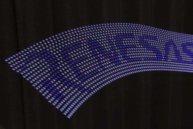
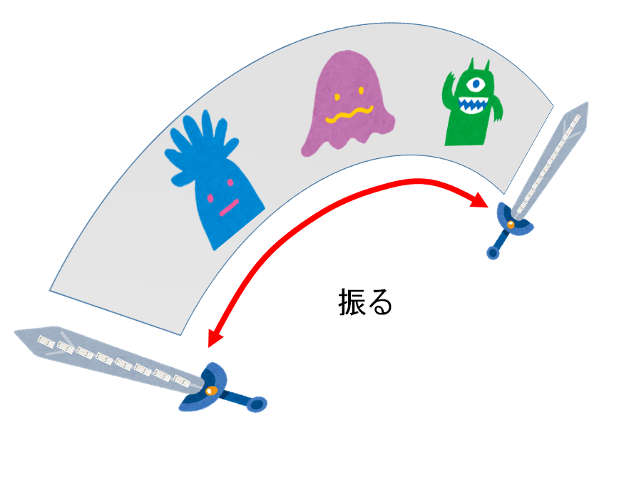
| About adventure Making of sword-shaped full color POV (Persistent Of Vision) using GR-KURUMI. POV means to describe pictures and characters by residual images.Holding up and down a sword, you can see pictures and characters in the air. This article is aiming at “making of GADGET” not only introduction.Using cardboards which is easy to manage for everyone for outer body. With dramatic presentations that use sounds etc…, make your original one.Going on your trip with your original sword. |
Structure (preparation before adventure)
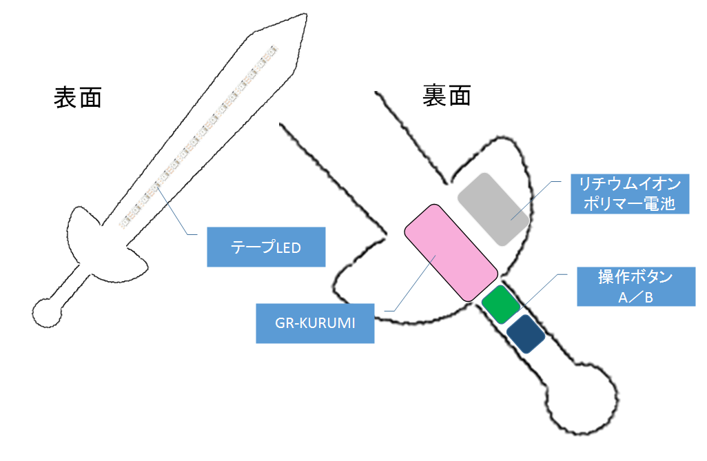
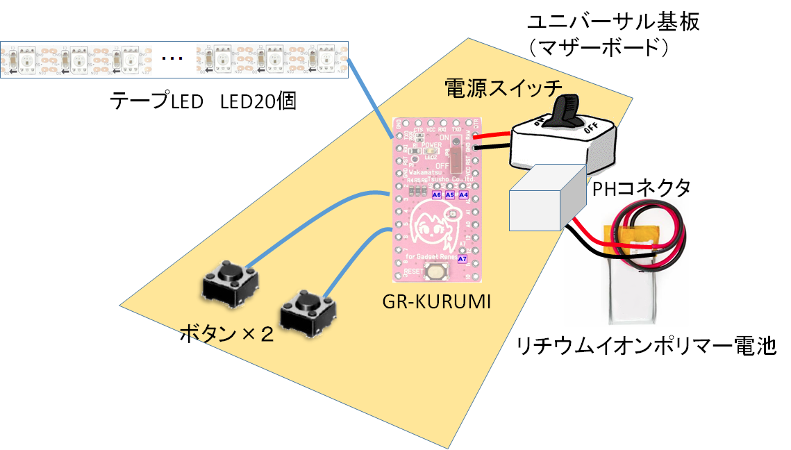
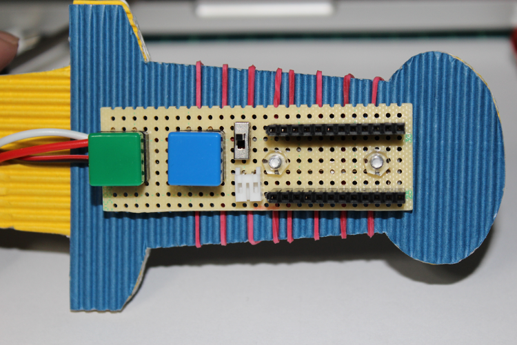
◆Whole picture
Sword-shaped POV has 20pcs of full color tape LED, is lighting on surface, controlled by GR-KURUMI.Put two buttonas(A,B) on backside for handling LED lighting.Using small size li-ion polymer battery run.
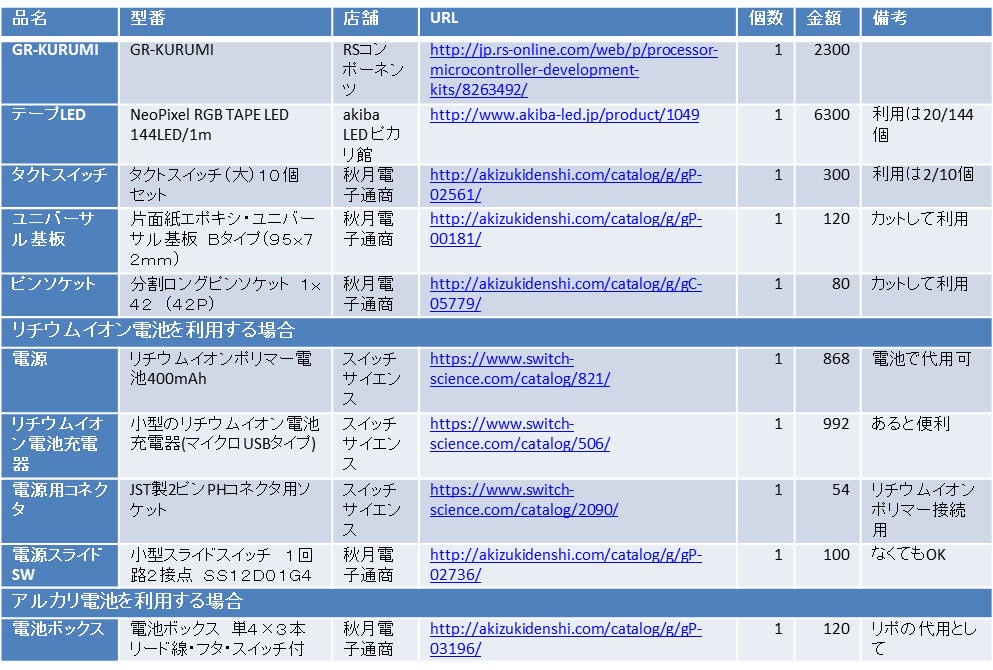
◆BOM
BOM.xlsx [ダウンロード]
Main components (Major players)
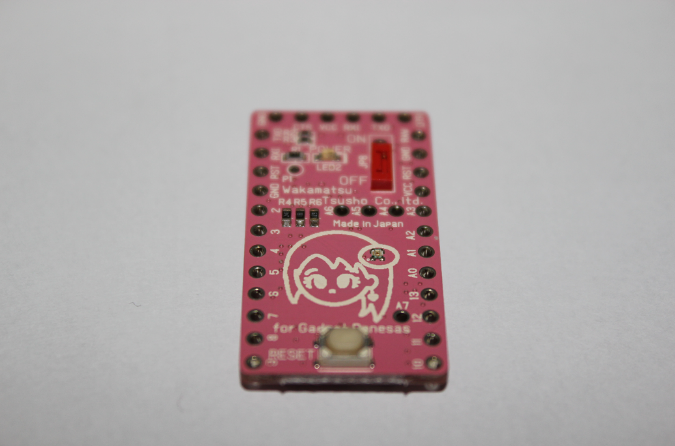
◆GR-KURUMI
Using GR-KURUMI,GR-COTTON is also OK.Downloading binary data generated by web compiler to write programs through USB serial converter module such as FTDI.
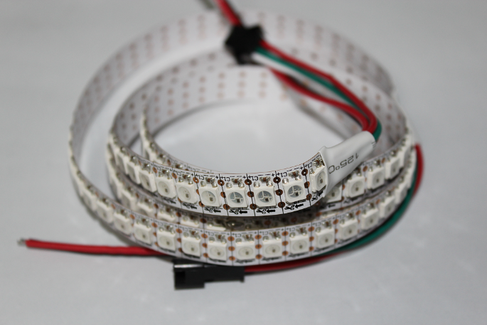
◆TAPE LED
Using full color serial LED tape with LED part number WS2812B.
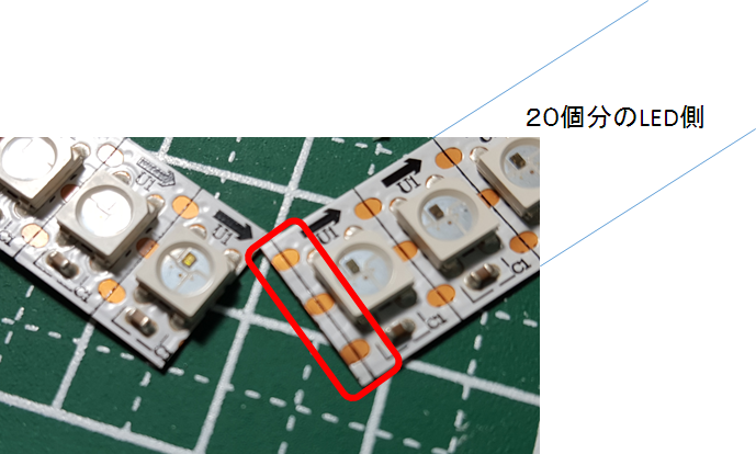
Narrow arrangement interval of LED brings out finer images.Cut tape and take 20pcs,however,it’s too many (a little expensive) to buy one reel,since it has 144pcs.Try to take 20pcs from the person who keep the rest. ※You may have some when you contact me.
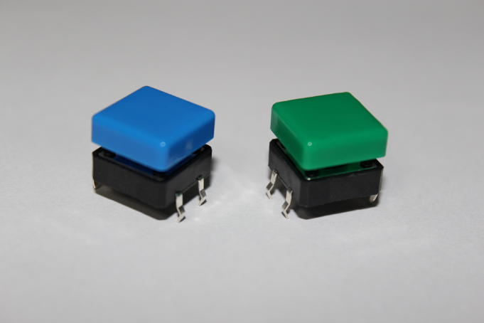
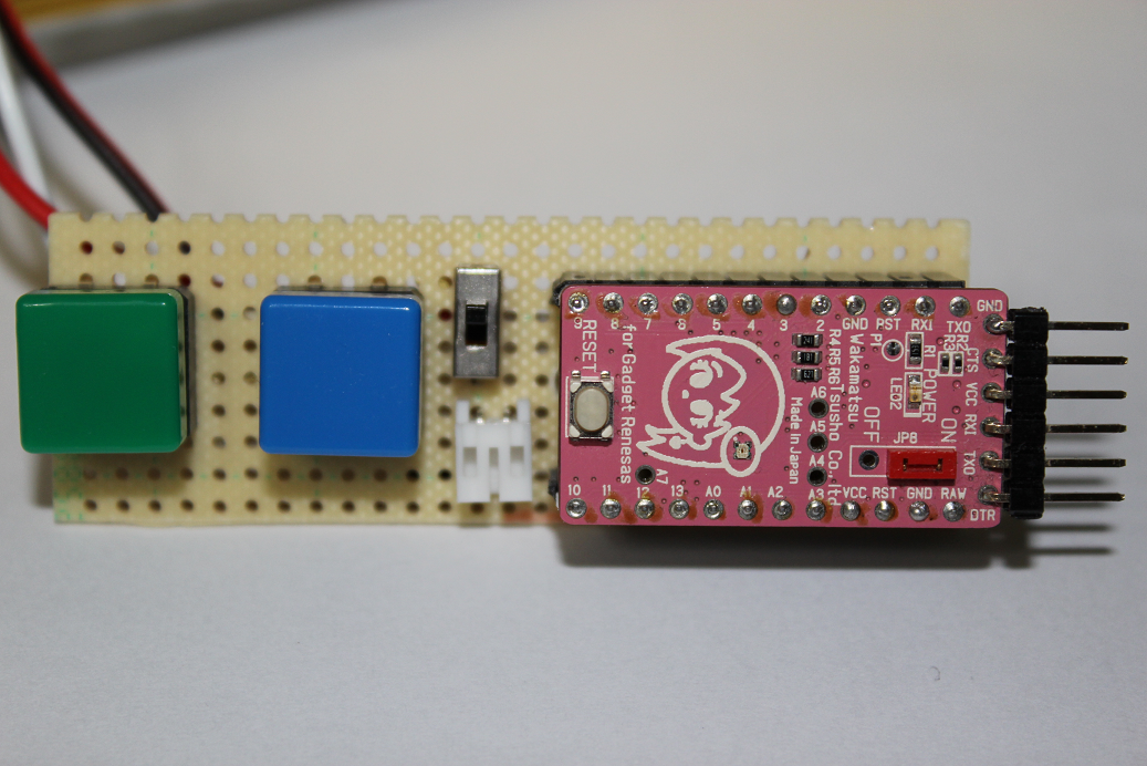
◆Tact switch
Be ready for two. A button : for trigger for starting descriptions B button: for changing of described contents. It’d be easier to handle with bigger buttons, replacable with the ones if you have on hand.
◆Li-ion polymer battery & Charger
A 3.7V output rechargeable battery (charger is required separately), is useful to create mobile type of GADGET due to its small size. GR-KURUMI goes well with this type of battery since its available voltage range is wide, ready to use without stepping up or down supply voltage. A PH connecter is required.
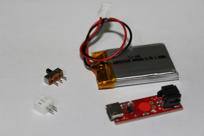
Either three of alkaline batteries (4.5V) or three of other rechargeable batteries are replaceable for long time run though the body weight gains.
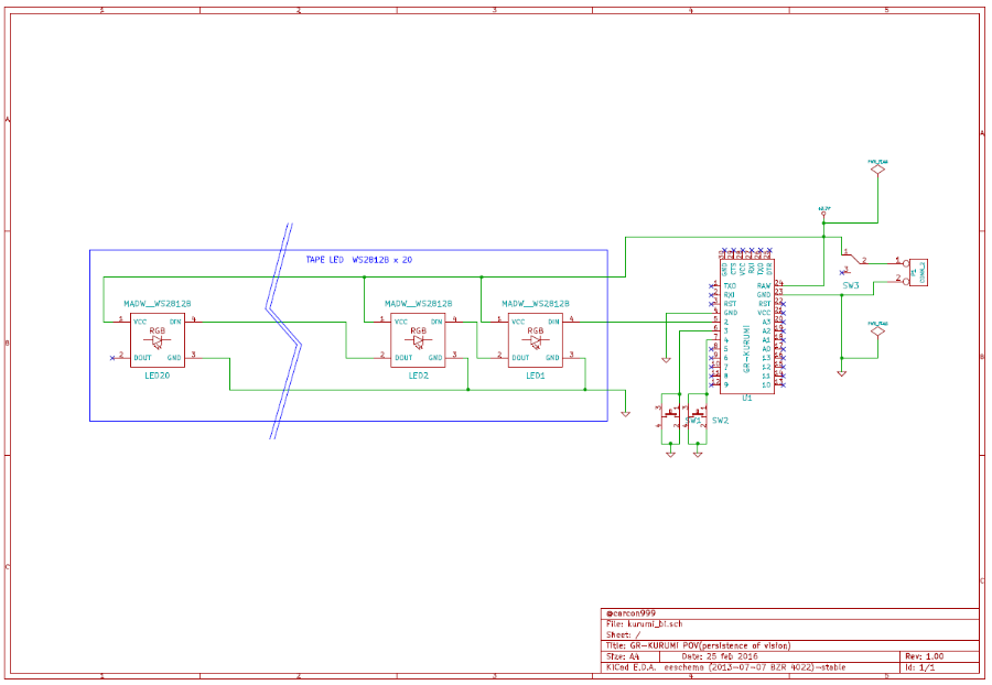
Schematic circuit diagram
If you modify and use the components with 3.3V run, please note the output voltage of polymer battery 3.7V. ※ LED operates within rating. Any ports are available since the programs consist of GPIO function only.
Schematic circuit diagram:schematic.pdf [download]
Making of hardware
◆Whole picture
Making a mother board from an universal board and attached it into sword-shaped body as well as tape LED.
◆Cutting tape LED
Cut off 140mm for 20pcs portion from a reel (144pcs/reel). Please don’t forget to leave some margin of LED pad for wiring, otherwise you have difficulty in soldering.
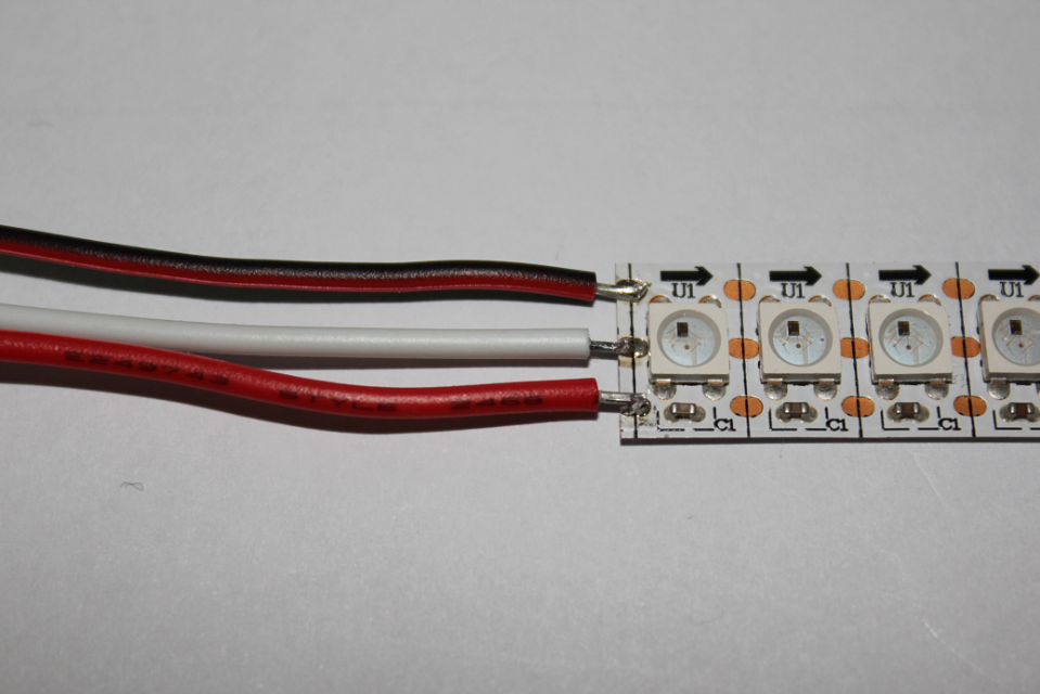
◆Wiring
Soldering three lines (GND, signal line, VCC) onto tape LED. Recommended preliminary soldering both pad on tape LED side and line materials.Please note the order of lines, direction since tape LED with WS2812B has several types.
When you wire onto mother board, fix it in the body first.
◆Making of mother board
With an universal board, make a mother board GR-KURUMI on board.Drawing the layout that all components except LED and power supply fits into the universal board.For fitting the buttons, rectangle is our recommendation (dimension: 25 x 72mm in this case). Satisfied circuit diagram, any kind of shape is fine.
◆Operation check
Let’s check with tester to see if power supply short out, the circuit between RAW and GND short out, and polarity of the power supply (battery) voltage is correct.Connected with the battery , check the polarity and the voltage of the circuit between RAW and GND without connected with GR-KURUMI. If you see 4.2V ~ 3.7V, that will be OK.
Making of body
◆Making of body
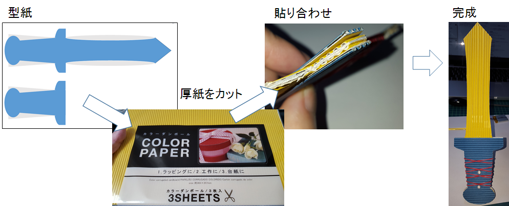
Here the sword pattern.
Sword body design:剣図案.pdf[download]
Use this sword pattern or draw your own design, the recommend length is longer than LED portion (=140mm).Recommended that several cardboards are sticked together for reinforcement of blade portion as children’s play considered.Feel free for your original design on cardboards.
In my case, took a color cardboard for \100, clip it out along pattern, strengthen with 4 piece of cardboard.
◆Fixing tape LED in the body
Fixed the tape LED with double sided tape, recommend 10mm-width one, available from stationery shop.
There are several methods to fasten the mother board, in my case、using plastic screws through the holes punched on board.After confirm the wiring position of LED, soldering it into mother board.
Software programming
◆Source code
kurumi_pov-2016.03.12.zip[download]
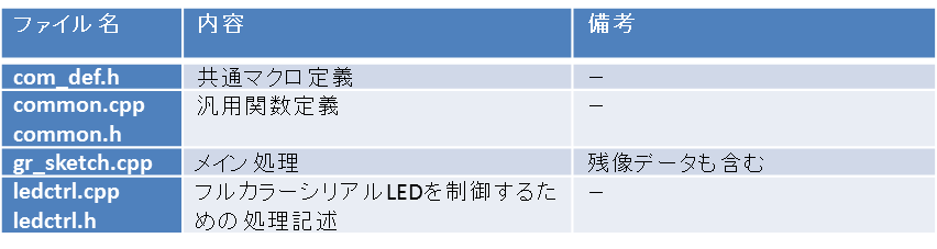
All source codes are available from download, feel free to use or modify. Files are divided into several ones for easy maintenance.
◆main loop
/**
* ボタンの押下を常時検出し、ボタンが押下されたら対応する処理を実施します。
*  ・Aボタン → 表示する画像の切り替え
*     ・Bボタン → LEDに画像データを出力する。(残像出力開始)
*
* @param    なし
*
* @retval なし
*
* @attention チャタリングで誤判定を抑制するために全8BITがON(OFF)になるのを検出します。
***************************************************************************/
void loop() {

    // キー押下検出処理
    key_scan();

    // Aボタンの押下検出
    if(pushed_flag_sw_a){
        pushed_flag_sw_a = false;

        // モードの切り替え
        view_mode++;
        if(view_mode > IMAGE_COUNT - 1){
            view_mode = 0;
        }
        pushed_counter = 0;

        // 10msだけ青LEDを点灯
        common_set_Kurumi_led(eBLUE);
        delay(10);
        common_set_Kurumi_led(eBLACK);
    }

    // Bボタンの押下検出
    if(pushed_flag_sw_b){
        pushed_flag_sw_b = false;

        // 50msだけ緑LEDを点灯
        common_set_Kurumi_led(eGREEN);
        delay(50);
        common_set_Kurumi_led(eBLACK);

        // 画像の表示
        draw(view_mode, pushed_counter);

        pushed_counter++;
    }

    delay(5);
}
Processing key scan in 5ms period. With the detection of A or B button being pushed, processing accordingly.In the case of the detection of B button, starting to send image data to LED. In the case of the detection of B button, sending image data to LED.
◆Processing LED
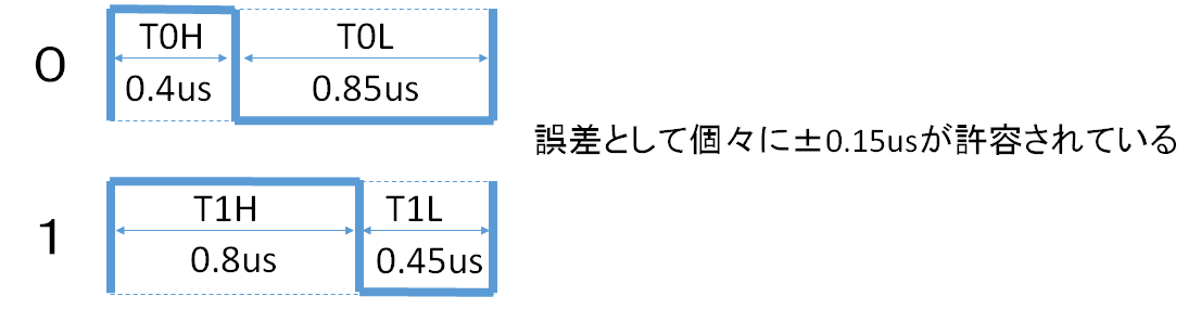
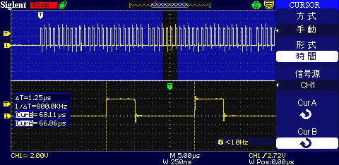
Each LED has four terminals only (VCC/GND/IN/OUT).Input 24 bits RGB serial data into IN terminal to emit one LED.Input 48 bits RGB serial data to emit two.To emit 20pcs of LED in a line, you need to have 480bits (24bits x 20pcs) of RGB serial data output from MCU side.Since transmission time is 1.25us per bit, would designate the color and display figures in 600us (480bits x 1.25us) for a line besides processing time.Please see the datasheet and the chart for timing , sending the waveform (0/1) for 24bits serial data. +/- 0.15us will be assumed as acceptable error range.
Tape LED (WS2812) capable of controlling timing at an early timing.So generate the timing with NOP, send the data with the timing prescribed by datasheet.(https://www.adafruit.com/datasheets/WS2812B.pdf)In my case, adjusted the number of NOP while observing waveforms by oscilloscope.
Output the data for a line (480bits), move to the next after a certain time (1ms).
Prohibit from an interrupt until all data is output otherwise the residual image won’t be shown up clearly,release after all data completed.
/**
* 指定されたデータを1列単位で連続して送信します。
*
* @param[in] img        画像データ
* @param[in] width    画像データの横幅
* @param[in] rvs        0:順方向  1:逆方向(反転)
* @param[in] wait     1列点灯時間(ms)
*
* @retval なし
*
* @attention 横幅はmax255としています。
* @attention 点灯時間は、振りの速さに影響されます。残像が間延びする場合は値を小さくしてください。
* @attention 割り込みが入ると綺麗に見えないので割り込み禁止で動作します。
***************************************************************************/
void ledctrl_draw_image(const RGB img[][TAPELED_NUM], uint8_t width, int rvs, int wait)
{
    DI();

    if(rvs)
    {
        // 逆方向でのデータ送出
        for(int y = width - 1 ; y >= 0 ; y--)
        {
            for(int x = 0 ; x < TAPELED_NUM ; x++)
            {
                ledctrl_set_rgb(img[y][x].r, img[y][x].g, img[y][x].b);
            }
            common_wait_ms(wait);                                     // wait ms
        }
    }
    else
    {
        // 順方向でのデータ送出
        for(int y = 0 ; y < width ; y++)
        {
            for(int x = 0 ; x < TAPELED_NUM ; x++)
            {
                ledctrl_set_rgb(img[y][x].r, img[y][x].g, img[y][x].b);
            }
            common_wait_ms(wait);                                     // wait ms
        }
    }

    EI();

    ledctrl_set_black();
}
ledctrl_set_rgb Call for the function, output the 24bits data.Defined TAPELED_NUM as 20 this time, output 480bits data with this loop.
◆Processing key_scan
/**
* key(プッシュボタン)をスキャンして押下判定を行います。
*
* @param  なし
*
* @retval なし
*
* @attention チャタリングで誤判定を抑制するために全8BITがON(OFF)になるのを検出します。
* @attention チャタリングの度合に応じて間隔を空けて呼び出してください。(5~20ms周期)
***************************************************************************/
static void key_scan(void)
{
    ////////////////////////////////////////////////////////////////////////////
    // key scan A
    ////////////////////////////////////////////////////////////////////////////
    status_sw_a <<= 1;
    status_sw_a |= digitalRead(SW_A);

    if(!pushed_mask_sw_a)
    {
        // all on -> pushed
        if(status_sw_a == 0){
            pushed_flag_sw_a = true;
            pushed_mask_sw_a = true;
        }
    }
    else
    {
        // all off
        if(status_sw_a == 0xFF){
            pushed_mask_sw_a = false;
        }
    }

    ////////////////////////////////////////////////////////////////////////////
    // key scan B
    ////////////////////////////////////////////////////////////////////////////
    status_sw_b <<= 1;
    status_sw_b |= digitalRead(SW_B);

    if(!pushed_mask_sw_b)
    {
        // all on -> pushed
        if(status_sw_b == 0){
            pushed_flag_sw_b = true;
            pushed_mask_sw_b = true;
        }
    }
    else
    {
        // all off
        if(status_sw_b == 0xFF){
            pushed_mask_sw_b = false;
        }
    }
}
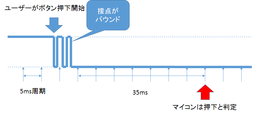
Processing eight-time matching detection by software instead of one-time HI/LOW detection.It’s aimed to prevent the contact point of button from wrong judgement when it bounds.Seeing if all 8 bits data suit with ON(0x00)/OFF(0xff) by bit-shift for detection.since the program check the port in 5ms period, push the button for 35ms at least otherwise the noise is assumed.
Residual image characters
Put four kinds of residual image data as sample. The height is fixed at 20 dots in line with 20pcs of LED, defined the value of each RGB on image table as it is.If you interchange the image data, rewrite the value on this table.Here the program of windows application by C# which can calculate the value automatically.Can attach it into image table by reading an image data.Please refer to the program of windows application which can be downloaded below. afterimgCreater.zip[download]
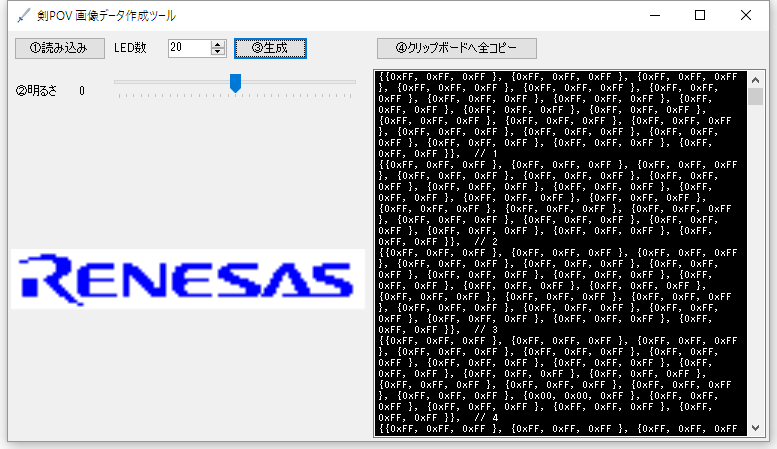
As for a full color serial LED, when a white color is output, power consumption is high (50mA at max).1A could be consumed to have all 20pcs of LED lit white.This window application has a useful function which can modify the brightness of whole image data. Recommend that you adjust on the brightness by this to save power consumption,try it in various ways.
◆Writing programs
Writing binary data released in the public, please refer to the URL for procedure.
http://japan.renesasrulz.com/gr_user_forum_japanese/b/weblog2/archive/2015/06/10/kurumi.aspx
Operation check (leave for adventure)
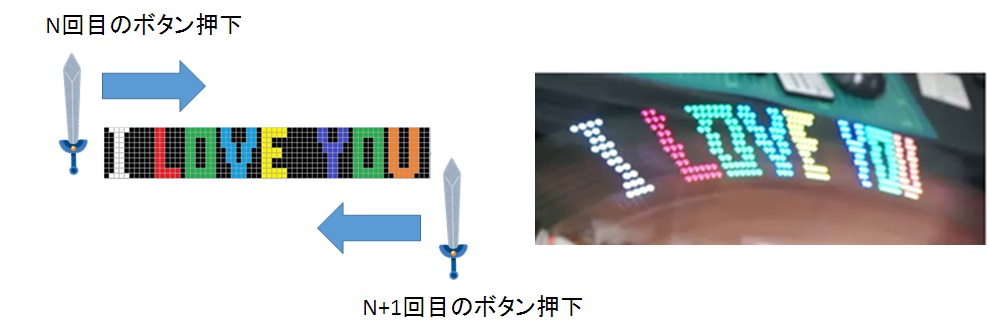
Connect with the battery for power on.Push the A button, LED lights emit in a moment.Push the A button again, swing to the right.Push the A button again, and swing to the left, right, left, right, left …..Something show up?
Push the B button, move to next image.Make various image data to leave for the adventure!
Summary
Active software engineer
Engaged in the development of medial system, embedded system for audio.
The hardware development, the industrial design drawing are one of my hobbies.Eager for contribution to the education field, such as submitting his writing for technical magazine.
Seeking for real ties,I also show up in the maker faire, starting up events etc…
Launched 「KIRAKI Light Core」 based on cloud funding.
https://www.facebook.com/kirakilight/ under construction as of Mar 2016
http://blogs.yahoo.co.jp/carcon999

Follow