
Title:Let's try the function on GR-KURUMI, analog input ADC vol.
Displayed Name:@chobichan
| Concept / Overview |
|---|
| Let's try the analog input ADC function! |
Handling analog signal by microcontroller
In real world, all sort of phenomena are filled with analog signal while MCUs are in the digital world. Analog signal needs to be converted into digital signal somehow.
An ADC ‘Analog to Digital Converter’ function, which converts analog signal into digital one, fortunately equipped with MCU in many cases, MCU can handle analog signals.
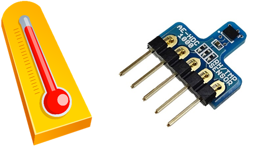
Or HDC1000, temperature-humidity sensor, also has ADC, MCU can use digital signals directly.
Low accuracy of analog signals
Remember learning how to use the scale when we are elementary school student.
Take an average by measurement several times or several rulers.
The degree of the scale for typical measuring tools are at variance.
In the analog world, every amounts has an error, which is unavoidable. The degree of measured values are unstable, of scale, the sensibility of visual inspection as well.
Even the scale of a ruler made of metal,it's known to expand or shrink depend on ambient temperature.
We can’t pursue the accuracy endlessly, it’s important to find an acceptable range, up to the xxx decimal place.
When you measure analog signals, set the accuracy in advance.

Roughness of digital signals
In digital world, defined clearly, the accuracy of the figure is infinite.
On the other hand,
An analog signal has continuity, every point has error range.
Think about resolution of ADC built in microcontroller.For example, the resolution of ADC on GR-KURUMI is 10bit which is allowed to show the figure in 1024 ways.
divide by 1024 gives 3.2mV. Converting into digital signal; 0~1023. 0 is 0mV. 1 is 3.2mV, 2 is 6.4mV….. 1023 is 3296.8mV. So what's 1.6mV going to be?The output of ADC, 1.6mV will be either 0 (0mV) or 1 (3.2mV), the error is 1.6mV against actual value. If the resolution of ADC is 11bit, 1.6mV will be 1. How about 0.8mV? If the resolution of ADC is 12bit, 0.8mV will be 1.
Converting from analog signal to digital signal, this approach of increment of resolution is often used to improve accuracy.However, in RL78/G13 case, the resolution of ADC is fixed at 10bit.

To improve accuracy on 10bit resolution of ADC, by converting analog signal several times, statistically we can set the 11bit.
This approach is like the way of measurement with scale several times. We must consider that we need to spend a lot of loads/money to improve accuracy.

Measuring temperature with a thermometer built in microcontroller
RL78/G13 on GR-KURUMI has built in temperature inside, we can see temperature easily.
Let’s try.
Nothing special. Generate new project on WEB compiler, realize the function in source code 'gr_sketch.cpp' automatically.
void setup() {
  //setPowerManagementMode(PM_STOP_MODE, 0, 1023); //Set CPU STOP_MODE in delay()
  //setOperationClockMode(CLK_LOW_SPEED_MODE); //Set CPU clock from 32MHz to 32.768kHz

  // initialize the digital pin as an output.
  Serial.begin(9600);
  Serial.print("Temperature: ");
  Serial.println(getTemperature(TEMP_MODE_CELSIUS)); //temperature from the sensor in MCU
getTemperature(TEMP_MODE_CELSIUS);
is the function which take temperature data with Celsius from a built-in thermometer.
Open this program on GR-KURUMI through COM port, output the temperature only once.
Measuring temperature with an analog sensor
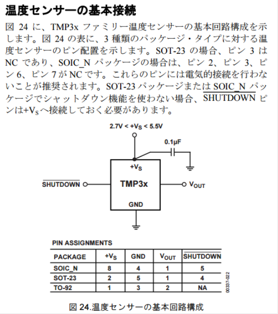
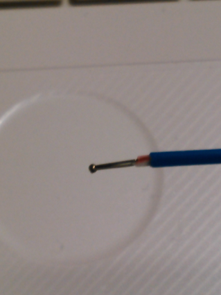
When we say analog temperature sensor, there are several types. When we say analog temperature sensor, there are several types. Thermistor, platinum are popular, here we use TMP36GT9Z, IC type. Since supply voltage range is 2.7V~5.5V, MCU can be used with 3.3 V supply voltage.
When outputting, sensor convert temperature into voltage in a ratio of 10mV per 1℃. Rising temperature by 1℃, 10mV increase in voltage.
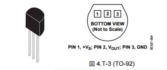
As for temperature sensor, usually making 25℃ a criterion since it’s normal temperature.
Since TMP36GT9Z is set at 750mA when it is 25℃, when the voltage taking from ADC convert into temperature, specify the reference point at 25℃. With this sensor, measure temperature range up to 50℃.
Output value by sensor is 1.25V when its 50℃.
Buy TMP36GT9Z from Marutsu.
http://www.marutsu.co.jp/pc/i/171271/
Setting the accuracy
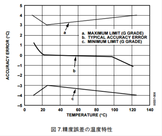
At the beginning, need to Know the accuracy on TMP36GT9Z. Datasheet shows the error range ±1℃ at 25℃, ±2℃ during -40℃~125℃. To recognize a change easier, set the accuracy to the first decimal place.
Connection with temperature sensor
Connect A0 port on GR-KURUMI with output of temperature sensor. As datasheet shows, prepare bypass capacitor.
Connect A0 port on GR-KURUMI with Vout of sensor.
Operation
Here is the sample code for the program which output temperature to serial regularly.
/*GR-KURUMI Sketch Template Version: V1.12*/ #include#define TMP36_PIN A0 #define VREF 3.3f //基準電圧。ここでは電源電圧(3.3v)を使用 void setup() { analogReference( DEFAULT ); //基準電圧の設定 Serial.begin(9600); Serial.print("Internal temperature:"); Serial.println(getTemperature(TEMP_MODE_CELSIUS)); //temperature from the sensor in MCU while( 1 ) { unsigned short tmp36US = analogRead(TMP36_PIN); float tmp36F = ((float)tmp36US * VREF) / 1024.0f; //一旦電圧に換算している tmp36F = ((tmp36F - 0.75f) / 0.01f) + 25.0f; //25℃を基準に計算している tmp36F = tmp36F + 0.05f; //小数点以下第2位で四捨五入 char buf[32]; sprintf( buf, "%2.1f", tmp36F ); String s = "External temperature:"; s += buf; s += "c"; Serial.println( s ); //temperature from the external ic sensor delay( 1 * 1000UL ); } } void loop() { }
Improving accuracy
Here is the output data as below.
In a ratio of 10mV per 1℃, rising temperature by 0.1℃, 1mV increase in voltage.
Considering that the resolution of ADC is 10bit, as I already mentioned, 3.2mV is the lowest figure digital signal can show.
Is there any good ideas to improve accuracy to the first decimal place?
The effective resolution come from standard voltage divided by ADC resolution.
As for standard voltage, RL78/G13 on GR-KURUMI has three options such as 1.45V standard voltage generated inside, outside as well as power supply voltage (VCC).
Please refer to the function "analogReference".
Arguments
DEFAULT:VCC
INTERNAL:Built in voltage 1.45V
EXTERNAL:Choose an option of “fixed at VCC on board”
Assume the standard voltage is 1.45V, resolution is around 1.4mV, we can see some progress.
However, as datasheet shows, internal voltage has an error range, 1.38V at minimum, 1.5V at maximum.
Though it’s more stable than VCC which is affected by possible fluctuation of supply voltage.
Usually, we take advantage of external standard voltage.
Unfortunately it's not available on GR-KURUMI.
There are many types of IC which allow to generate standard voltage. Pick from them on demand.
Again, to improve accuracy, rather than the method of using hardware, extract the necessary data compensated from the deviation such as average of taking analog signal data several times, running mean, least-squares method.
Verifying the measurement of the temperature
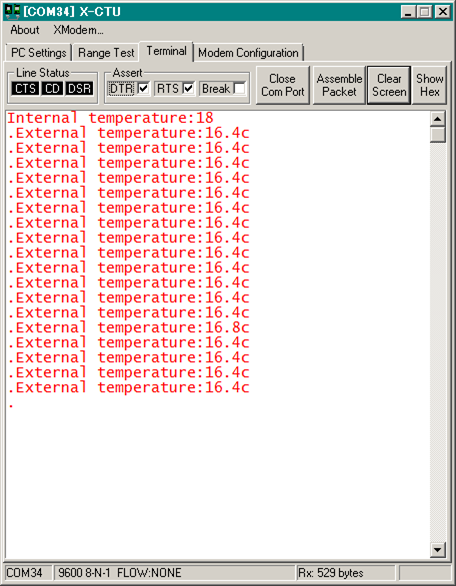
How do we check whether the measured temperature by GR-KURUMI is corrected? A standard measuring tool or thermometer is required for comparing.
Checking to see the error range of the thermometer widely appeared on the market.The error range ±1℃~2℃ is normal at 25℃。
Other temperature sensors of IC type as well.
Searching high-precision measurement of temperature on the web, found this document. Click here.
http://www.el.gunma-u.ac.jp/~kobaweb/lecture/hiaccusensor.pdf
An error range ±1℃ would be no problem in the case of measurement of room temperature. ※Need to pick higher – precision one to reduce the electrical charges for air conditioner even a little.
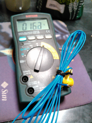
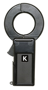
As standard, found the tester with thermometer function and its accessory K type of heat electric body in my house. K- type of heat electric body is a small sensor made by bonding together sheets of two different metals. As picture show, fitting on the tip of a cable in a bared state.
IC type temperature sensor is much bigger than K- type of heat electric body, the difference in size affect on the one in thermal capacity.
Bring in 50℃ ambient temperature, IC type temperature sensor react slow while K type of heat electric body react quickly.
More over K type of heat electric body is sensitive to the slightly flowing air.
Comparing the two, the same condition is required.
As one of methods, standard thermometer and evaluation object are packed with cotton and aluminum foil to avoid wind, take some time to compare the two altering temperature in refrigerator or heating hotplate slowly.
Record the output of the IC temperature sensor at each temperature and plot in the graph. In normal temperature range, as the output of IC temperature sensor tends to become the straight line on a certain degree, Let’s multiple the value coming from ADC by compensate coefficient taking from plot to approach actual measurement figure.
Notice on mounting on board
Even improved accuracy or compensated, if IC temperature sensor is mounted near the devices which consume big power such as micro controller, wireless module or power supply, it would be affected by them and can’t measure temperature correctly.
Keeping away from the device consuming big power, need to mount the position not filled with heat.
Also keep away from the case as IC temperature sensor is affected by heat capacity if it adhere to the case.
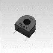
Handling AC signal
The trans has been distributed to measure AC current, widely used for the electronic kit because of energy-saving boom.
http://www.u-rd.com/
http://www.multimic.com/
Also used for measuring consumption current on electric apparatus or current on switchboard.
The signal which ADC handle on GR-KURUMI would be DC in 0~3.3V or 0~1.45V.
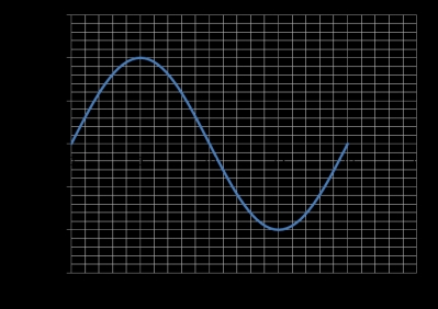
When measure AC, signal swing in a plus or minus direction. Acting isolation, take trans as picture shows, convert the output current at secondary side into voltage, then apply DC bias on the voltage so that microcontroller can handle. Take advantage of ADC dynamic range by adjustment of middle point and oscillation. For example, If standard voltage is 3.3V, set the middle point as 1.65V, oscillation as ±1.5V at maximum current.
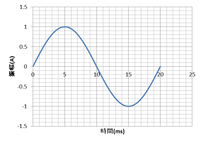
The value of the AC is calculated by Root Mean Squire (RMS).
Graph shows the simulation plot that the oscillation of current is assumed to be ±1A in the peak.
Actually, it's approximately 0.707Arms.
Actual current waveform, it won’t be sine wave in good shape like this. Electric apparatus using switching power supply has a more complex waveform.
This graph in excel file consist of 32pcs of data per one wave, described with plot by every 0.625ms. In East Japan, the frequency of power supply is 50Hz, 20ms period. 20ms divided by 32 data equals 0.625ms.
When described in excel file, go backward the process that set the oscillation from the current value of 0.707Arms, then draw up 32 data, plot this data to draw sign waveform.
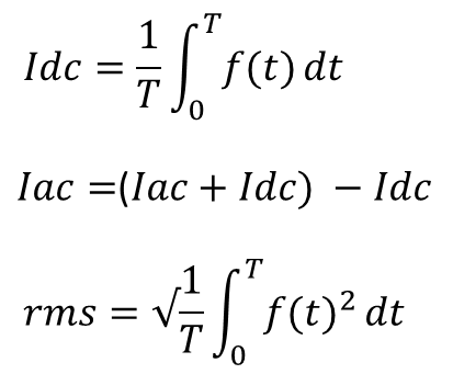
Using ADC, let AC waveform convert into digital data by every 0.625ms. Remove the DC portion from each data due to applying DC bias.
Definition of AC waveform is the waveform which the total amount of the oscillation will be zero for a period, if add digital data for a waveform, only DC portion will be left, average will be the DC value which is applied DC bias. Please refer to the formula in the left.
If remove the DC portion from original data, only AC portion will be left. Average of integral each value’s squire for AC portion per one wave, take root of the value as actual data.
Please refer to he formula in the left. Provisionally, take AC waveform as digital data with 1/32 period of one wave,The more complicate actual waveforms are,, the more data is needed to be converted with shorter period and higher resolution.
Automation of taking analog signal
Taking AC is necessary to be executed with right period and high frequency.
With analogRead, it’s difficult to perform with a fixed time period and a constant CPU load since software is trigger in conversion to digital data. However RL78/G13 will be convert it automatically, storage it into RAM since it has timer coincide with ADC and DMAC.
Let’s try this function.
※This function is not supported by library, need to set the resister of the peripheral function by yourself.
Direct access to the register of RL78/G13 (ADC, DMA etc.)
As an advantage of library conforming to Arduino, even you don’t have much knowledge about hardware of RL78/G13, it would help operation in its own way.
Apart from library support, let’s operate microcontroller.
Handling register, include these file as below.
#include
#include
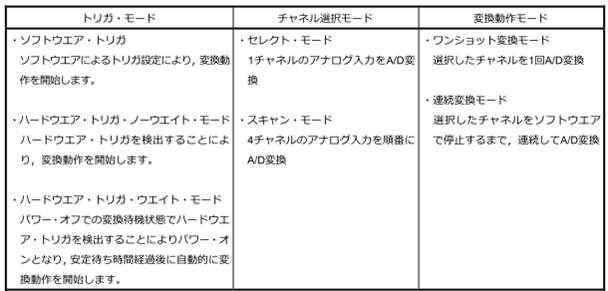
◆The select of ADC trigger
Here is the block diagram for ADC on RL78/G13. Please refer to the point in the red circle for the input for the trigger of ADC conversion.
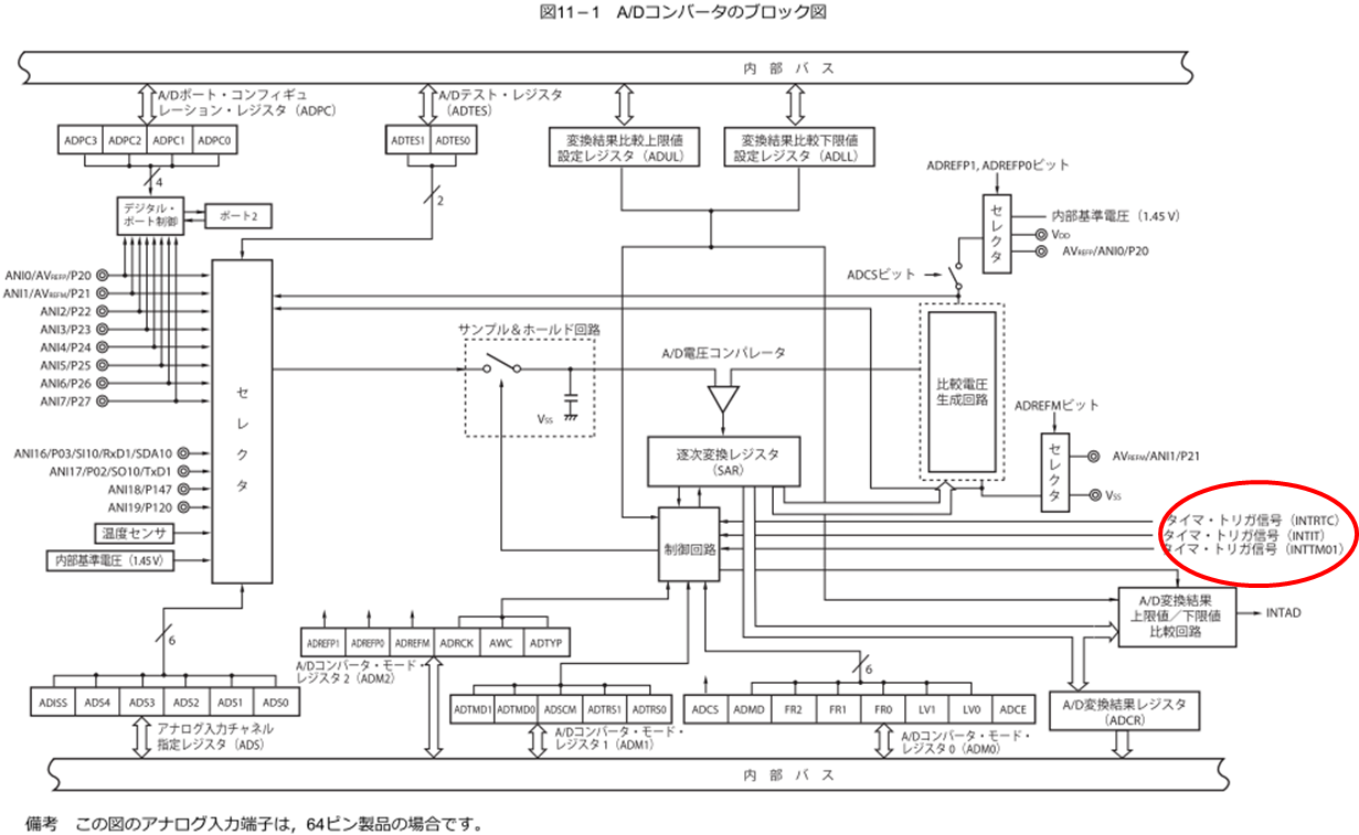
The interruption generated at RTC would be a trigger for INTRTC. The interruption of timer 0, channel 1 would be a trigger for INTTM01.
The interruption of 12bit interval timer would be a trigger for INTIT. INTRTC is not available since RTC is going to be used as clock.As for INTTM01, original oscillation of timer is 32MHz, the system clock generated by high speed on-chip oscillator.
Accuracy of oscillation is within +/-1% in normal temperature range if operation voltage is 3.3V.
INTIT can’t be used since it’s working on management per millimeters unit.
INTTM01 is used by divided original oscillation. The issue is if we can set the ratio by which original oscillation is divided without residue.
Divided 32MHz by 50Hz x 32 gives you just 20000.
INTTM01 is an option for trigger.
Showing how to reset the value of timer as below.
void TMR01Init( unsigned short tdr01 )  //タイマー0、チャネル1初期化
{
  PER0.BIT.tau0en = 1;  //timer unit 0 enable

  TDR01.tdr01 = tdr01;
  /*0x50:CKm3=125khz,CKm2=16mhz,CKm1=1mhz,CKm0=32mhz*/

  TMR01.BIT.bit15 = 0;  //CKm0 select
  TMR01.BIT.bit14 = 0;  //CKm0 select
  TMR01.BIT.bit12 = 0;  //CKm0 select
  TMR01.BIT.bit11 = 0;  //SPLIT 16bit timer
  TMR01.BIT.bit10 = 0;  //STS012 only software trigger
  TMR01.BIT.bit9 = 0;  //STS011 only software trigger
  TMR01.BIT.bit8 = 0;  //STS010 only software trigger
  TMR01.BIT.bit7 = 0;  //CIS011 rise
  TMR01.BIT.bit6 = 0;  //CIS010 rise
  TMR01.BIT.bit3 = 0;  //MD013 interval timer
  TMR01.BIT.bit2 = 0;  //MD012 interval timer
  TMR01.BIT.bit1 = 0;  //MD011 interval timer
  TMR01.BIT.bit0 = 0;  //MD010 no interrupt

  TOE0.BIT.bit1 = 0;  //disable TO01 output
  //TIM01 interrupt enable 0x2e
  IF1L.BIT.tmif01 = 0;  // interrupt request flag clear
  //  MK1L.BIT.tmmk01 = 0;  // interrupt mask flag -> enable
  MK1L.BIT.tmmk01 = 1;  // interrupt mask flag -> disable
  PR11.BIT.tmpr101 = 1;  // interrupt priority bit1 -> min
  PR01.BIT.tmpr001 = 1;  // interrupt priority bit0 -> min

  TS0.BIT.bit1 = 1;  //channel1 start
}
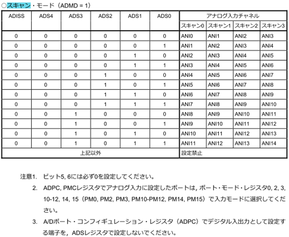
◆Using scan mode
ADC on RL78/G13 has scan mode which can convert several analog inputs all at once.
It’s helpful when you need to handle several inputs.
Please keep in mind the followings.
Under scan mode function, make sure to select four channels, moreover there is a constraint on channel combination.
※Please refer to the chart.
Please don’t select the terminals having set as digital for conversion channel.
Let’s scan ANI0~ANI3 this time
※In GR-KURUMI case, ANI0 is connect to 3.3V, ANI1 connected to GND. Both ANI2 and ANI3 are available for analog input. Triggering as INTTM01 50HZ x 32 , generate the conversion data with 8byte by every 0.625ms.
Showing how to reset the value of ADC.
void adInit( void )  //ADCの初期化
{
  PER0.BIT.adcen = 1;  //A/Dコンバータで使用するSFRへのリード/ライト可

  ADPC.BIT.bit0 = 1;  //AIN0(P20) to AIN3(P23) for analog input
  ADPC.BIT.bit1 = 0;  //
  ADPC.BIT.bit2 = 1;  //
  ADPC.BIT.bit3 = 0;  //
  PM2.BIT.bit0 = 1;  // AIN0(P20) to AIN3(P23) for analog input
  PM2.BIT.bit1 = 1;  //
  PM2.BIT.bit2 = 1;  //
  PM2.BIT.bit3 = 1;  //

  ADM0.BIT.adce = 0;  //A/D電圧コンパレータの動作停止
  ADM0.BIT.adcs = 0;  //変換動作停止
  ADM0.adm0 = 0x40;  //scan,fclk/64

  ADM1.BIT.bit7 = 1;  //ハードウエア・トリガ・ノーウエイト・モード
  ADM1.BIT.bit6 = 0;  //ハードウエア・トリガ・ノーウエイト・モード
  ADM1.BIT.bit5 = 1;  //ワンショット変換モード
  ADM1.BIT.bit1 = 0;  //INTTM01
  ADM1.BIT.bit0 = 0;  //INTTM01

  ADM2.adm2 = 0x00;  //A/Dコンバータの+側の基準電圧源の選択
  //VDDから供給
  //A/Dコンバータの-側の基準電圧源の選択:VSS
  ADM2.BIT.adrck = 0;  //
  ADLL.adll = 0x00;
  ADUL.adul = 0xff;
  delayMicroseconds( 2 );  //wait for adc stability
  ADM2.BIT.adtyp = 0;  //10ビット分解能

  ADS.ads = 0x00;  //scan ANI0->ANI1->ANI2->ANI3

  //ADC interrupt enable 0x34
  IF1H.BIT.adif = 0;  // interrupt request flag clear
  //  MK1H.BIT.admk = 0;  // interrupt mask flag -> enable
  MK1H.BIT.admk = 1;  // interrupt mask flag -> disable
  PR01H.BIT.adpr0 = 1;  // interrupt priority bit1 -> min
  PR11H.BIT.adpr1 = 1;  // interrupt priority bit0 -> min

  ADM0.BIT.adce = 1;  //A/D電圧コンパレータの動作start
  delayMicroseconds( 2 );  //wait for adc stability
  ADM0.BIT.adcs = 1;  //wait trigger
}
◆Using DMAC
The data converted by scan mode will be signal-processed after it’s transferred into memory.
To have AC wave form signal processed, the data is required for a wave portion. It’s assumed to be 32 data this case.
For scan mode, 32 x 4 x 2byte of the data is transferred to memory.
DMAC 'Direct Memory Access Controller' would be help you.Under specified condition, DMAC automatically transfer the data from peripheral I/O to memory or from memory to peripheral I/O, instead of CPU.
The interruption from ADC is a trigger for DMAC this time.When the data transfer is completed preset number of times, DMAC can happen interruption to CPU.CPU can execute other tasks until the data transfer is complete, process the data later. As of setting of DMAC, original data is data-register of ADC and transferred to SRAM area secured in global variables.The size of data is 16bit, the times of transfer is 32x4times.
Laminate buffer for data storage, in order to prevent it from being overwritten by DMAC while CPU signal processing.
void dma1Init( void ) //DMAC初期化
{
DRC1.BIT.den1 = 1; // dma enable
unsigned long temp = (unsigned long)&ADCR.adcr;
DSA1.dsa1 = (unsigned char)temp; //sfr address set
temp = (unsigned long)currentBuffer;
DRA1.dra1 = (unsigned short)temp; //sram address set
DBC1.dbc1 = AD_SAMPLE_SIZE; //number of conversions
DMC1.dmc1 = 0x21; // trigger is ad conversion
//DMA1 interrupt enable
IF0H.BIT.dmaif1 = 0; // interrupt request flag clear
//__asm__("clr1 IF0H.3\n\t"); // interrupt request flag clear
MK0H.BIT.dmamk1 = 0; // interrupt mask flag -> enable
//MK0H.BIT.dmamk0 = 1; // interrupt mask flag -> disable
PR10H.BIT.dmapr11 = 1; // interrupt priority bit1 -> min
PR00H.BIT.dmapr01 = 1; // interrupt priority bit0 -> min
DRC1.BIT.dst1 = 1; // dma start and wait trigger
}
void dma1Int( void ) //割り込み処理
{
currentBufferUpdate++; //バッファが更新された事を示す変数
unsigned long temp = (unsigned long)¤tBuffer[currentBufferUpdate & 1];
DRA1.dra1 = (unsigned short)temp; //sram address set
DBC1.dbc1 = AD_SAMPLE_SIZE; //number of conversions
DRC1.BIT.dst1 = 1; // dma start and wait trigger
}
Registration of user interrupt
For procedure for interruption, please refer to interrupt_handlers.c under gr_common/RLduino78/portable/e2studio/RL78
DMA1 interruption will be INT_DMA1.
This is the program calling for procedure of DMA interruption.
//0x1C
extern void dma1Int( void );
void INT_DMA1 (void)
{
dma1Int();
}
【The example for procedure of triggering ADC】
This is the program for procedure of triggering ADC.
Actual signal processing is not mentioned.
#define AD_OVER_SAMPLE_RATE 32
#define AD_OVER_SAMPLE_MULTI 4
#define AD_SAMPLE_SIZE (AD_OVER_SAMPLE_RATE * AD_OVER_SAMPLE_MULTI)
unsigned short currentBuffer[2][AD_SAMPLE_SIZE]; /*AD変換後の電流チャネルのDMAの転送先。2ウインドウ構成とする*/
volatile unsigned short currentBufferUpdate; /*DMA転送完了割り込みの中で更新されるフラグ。*/
volatile unsigned short oldUpdate = currentBufferUpdate; /*DMA転送完了フラグと比較する変数*/
adInit(); /*ADC初期化*/
dma1Init(); /*DMA初期化*/
TMR01Init( 32000000UL / 50 / 32 - 1 ); /*タイマー初期化。32MHzのシステムクロックから50Hzの32倍オーバーサンプリングタイミングを発生。*/
General hard engineer... occasinally writing for technical magazine.

Follow