
Title:Wireless Toy Phone
Displayed Name:Yusha Kobo
| Concept / Overview |
|---|
| I would like to introduce how I made a wireless toy phone which I presented at Renesas Night 7. A “Secret Futuristic Gadget” appearing in an anime film inspired my creation. The basic idea was that you could talk from an even longer distance if you eliminated the wire or string connecting the tin can phones we played with in our childhood. Of course, there are already many examples of instruments allowing us to converse from a distance without wires or strings or cables, including radios, transceivers, and cell phones. The point of my apparatus is that on their own, vibrations from one paper cup, i.e. your telephone, can reach another person’s paper cup, achieving a wireless result. |
Mechanism
The basic mechanism is incredibly simple.
(1) First, just attach a piezoelectric device to the bottom of the paper cup. The additional pressure from the device will result in conversion to voltage. Therefore, if you speak facing the paper cup, the vibration from your voice will be carried from the cup to the piezoelectric device, producing a wave of voltage. In other words, the pneumatic oscillation (the voice) is converted to an electric signal.
(2) This voltage transformation is read by the GR-KURUMI analog port and changed into digital data. In this case, the voltage from 0V to 3.3V is divided into 256 steps and expressed as 8-bit data.
(3) Next, we use XBee to send data to the receiver’s GR-KURUMI.
(4) Data received by the receiver is output as analog and converted back to voltage vibration. Earlier, the piezoelectric vibration was converted into voltage vibration, but you can do this the other way around as well. In other word, the piezo device is deformed by voltage change. So, the paper cup vibration due to the piezoelectric effect generates the sound of the voice.
Finalize specifications
If you have used Arduino or other GR boards, you may already have some idea of how the sketch should be made based on the above description.
The sender writes the value read in analogRead in a serial transmission, while the receiver uses analogWrite to read the value also in serial. Neither a special protocol nor data format are required; rather, a simple format is used.
The last thing that needs to be done is to decide the frequency for the voice and how many steps it will be divided into. I used XBee Series 1 for communication in the project, so I set the maximum serial speed to 115,200bps.
I set the voltage split (quantization) to 8 bits in 256 steps allowing a maximum of 14,400 cycles per second. To leave plenty of time, I set it to 4,000 cycles per second—a sampling frequency of 4kHz.
Incidentally, normal telephone transmission uses 8-bit quantization with an approximate sampling frequency of 8kHz. Using a piezo electric effect element means voice quality is not great, but in this case, simply understanding what was being said was good enough.
If another form of transmission is used other than XBee, you may need to make appropriate adjustments.
◆ Specifications
| Serial (ZBee baud rate) | 115,200bps |
| Quantization | 8bit |
| Sampling frequency | 4kHz |
Avoiding use of a switch
A silly switch on a “Secret Futuristic Gadget” would not be cool… Well, that might be overstating things, so I installed switch for mode changes according to the angle during use.
I settled on three modes: send, receive, and sleep. Phones normally do not require a switch from send to receive, but since this gadget uses a shared piezo electric effect element, switchover capability was required. As a rule, users should say “over” after they finish speaking, an indication for the other side to speak, so this shouldn’t be a problem.
When people actually use the gadget, the angle setting might require an explanation.
One needs to tilt the “phone” gadget a bit downward when speaking.

The gadget should be more or less horizontal when listening.
The gadget should be set on a flat surface when not in use.
Determining the tilt angle
The addition of an accelerometer helps clue users as to the correct angle to hold the gadget when speaking or listening.
The accelerometer is attached horizontally on the base of the paper cup, with the Z axis facing upward.
The gravitational acceleration normally decreases, but moves reverses acceleration when the gadget is not in use, so if the paper cup is faced upward, the sensor shows X and Y as 0, with Z as a positive value. When Z approaches 0, the result is free fall.
To calculate the tilt angle of the paper cup in this situation, you have to find angle θ between the XY surface and the acceleration vector.
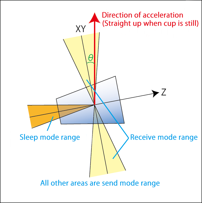
You can determine θ as shown in the sketch below.
xy = (fabs(X)+fabs(Y)); // x-y plane acceleration
if(xy){seeta = atan(Z/xy)*180/PI; // z-xy angle}else{seeta = (Z>0) ? 90 : -90;}
The variable seeta is gives a value of -90 to 90 degrees.
0 degrees is the horizontal level, so remaining within a ±20 degree range will guarantee receive mode. When the phone gadget is facing completely downward the angle will be -90 degrees. So, we can say anything under -80 degrees is sleep mode. Any other level or angle is send mode.
LED Indicators
The previous section discussed switching among receive, sleep, and send modes. However, using the gadget is awkward if one is unaware of which mode is functioning at the moment. I tried installing a tape-style full-color LED light to indicate which mode is functioning at any given time.
Click here for a video of the LED tape in action.
Click here to see an example of the full-color tape-style LED.
And here is a really handy LED controller.
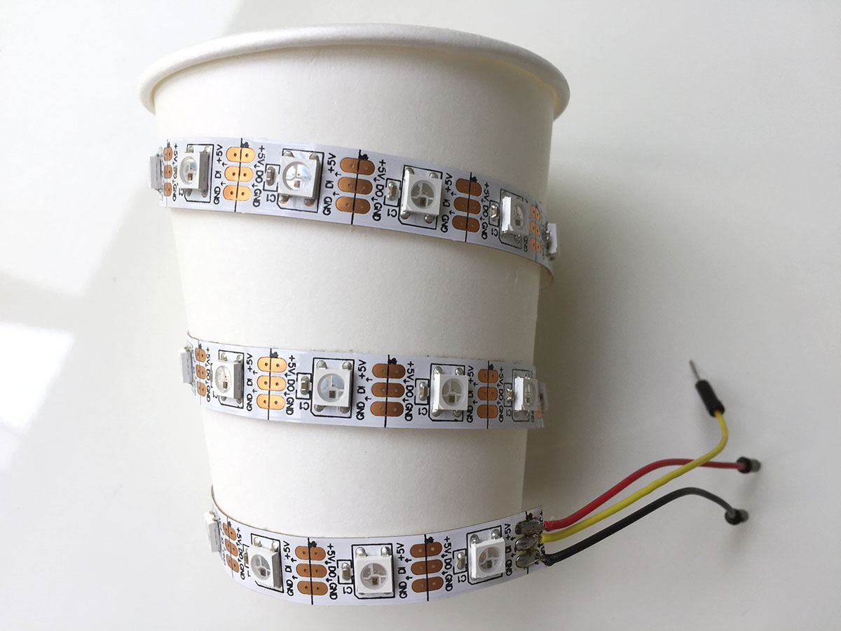
The controller is actually a kit, but I only used the 8-pin IC. This controller can be used to control up to 32 WS2812 drivers, so I halved 1m (60 LEDs) of tape into 2 segments of 30 LEDs. I wrapped the tape around the paper cup. The idea was to get data to flow in the same direction that light is transmitted.
Parts
The parts required to produce what we have described thus far are shown below.
If you don’t use a switch based on an accelerometer, you can choose a tactical or other preferred type of switch to change modes. Since you must make two “phones,” you naturally need to purchase two of everything.
・GR-KURUMI
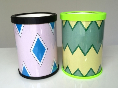
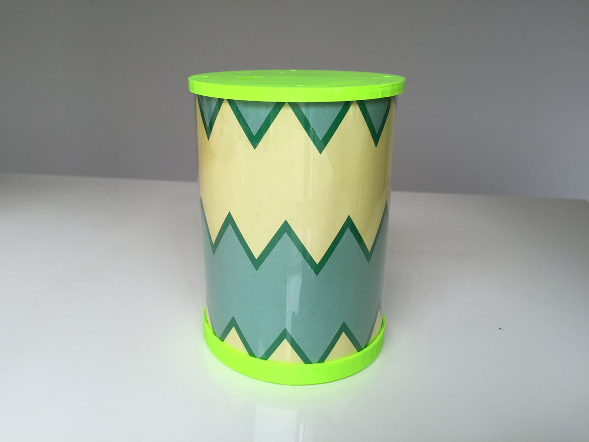
・Paper cup (approximately 8cm in height)
・Piezo electric effect element 7BB-35-3LO (with a lead)
(Suzusho, Ltd. http://www.suzushoweb.com/category_2.php?c2_id=189)
・XBee Series 1
(Akizuki Denshi Tsusho Co., Ltd. http://akizukidenshi.com/catalog/g/gM-06505/)
・Lipo battery
・3.3V regulator
・Electrical resistor (1MΩ)
・*Accelerometer ADXL362
(Strawberry-Linux https://strawberry-linux.com/catalog/items?code=12111)
・*Serial LED tape
(Switch-Science https://www.switch-science.com/catalog/1399/)
・*LED controller
(Switch-Science https://www.switch-science.com/catalog/1740/)
※ *Optional
A universal substrate, various connectors, and miscellaneous wiring may also be necessary.
Circuit Diagram
Here is the circuit design for the wireless toy phone.
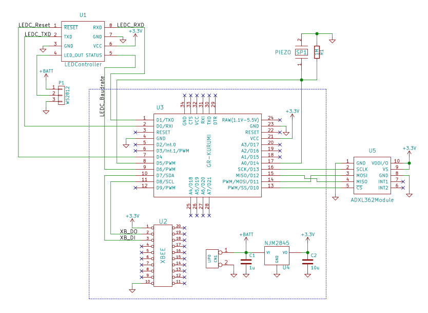
The area enclosed in the blue dotted lines is the base board and will be described in the next section.
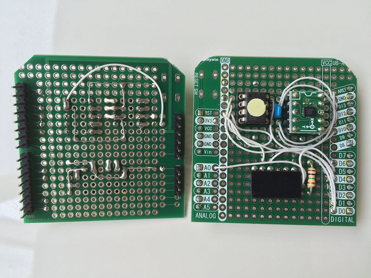
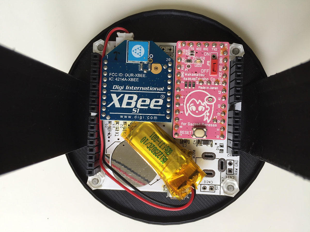
Base Board
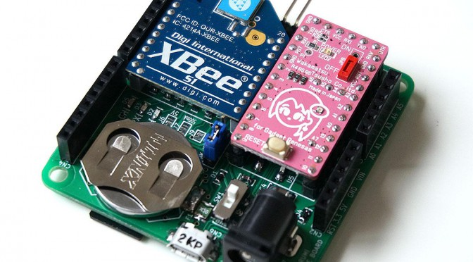
Although this is not specifically for this project, but I made a base board prototype onto which I could mount CBee, a Lipo battery, MicroSD card slot, USB serial converter (FTDI), and the like to make GR-KURUMI easier to handle. This substrate really helps simplify wiring, so by all means, give it a try.
KURUMI Baseboard Ver. 1.01 (download)
The base board data can be used as is when ordering. I recommend Switch-Science PCB (https://www.switch-science.com/pcborder/) and ELECROW (http://www.elecrow.com/5pcs-2-layer-pcb-p-1174.html), both of which are reasonably-priced. The base board should be 5x5cm, and the cheapest version can be ordered from the respective websites.
This substrate has a number of functions, but you can simply install the parts required for your particular use. You can find the various functions described on the BOM list enclosed with the board, and simply install the parts you need.
For example, this particular gadget requires installation of parts for the main board, a LIPO battery, a 3.3V regulator, a USB serial converter, and XBee. You can also add a USB serial converter and USB connector to directly connect a computer, as well as a LIPO charger, if you would like to recharge a LIPO battery.
The circuit diagram for this gadget show XBee and serial transmission using Serial 1 on GR-KURUMI. For this base board, jumper wires J1 and J2 should be shorted. This will connect GR-KURUMI and XBee. Parts which are missing from this substrate can be mounted on the universal board, but the board’s pin-out assignment must Arduino-compatible. Using an Arduino-compatible universal board makes things easier. I recommend the UB-ARD03 universal board for Arduino by Sunhayato Corp.
XBee Configuration
Next, you need to configure the XBee ID and baud rate. Configuration is set at 9600bps as default, but it should be changed to 115200bps for this gadget. The ID must be properly set in order to avoid crossed wires.
XBee is normally set with XCTU software. However, I prefer the easier way of using AT command in TeraTerm or similar terminal software if all you need to do is set the ID and baud rate. It is just a matter of preference, so if any of the products listed below seem too troublesome, by all means, proceed with XCTU.
XCTU download page: http://www.digi.com/support/productdetail?pid=3352
The explanation below applies to TeraTerm by Windows. If using a Mac, reload appropriately or use XCTU.
Connect XBee to your computer with a USB interface kit (http://akizukidenshi.com/catalog/g/gK-06188/) or similar product.
Use TeraTerm to connect XBee. The settings are shown here. Set the line feed code receive to CR+LF, and select local echo (on).
Serial configuration should remain as default, but confirm with the settings here.
In TeraTerm, input +++, wait 1 second without pressing Enter, and “OK” will be returned.
+++OK
At this point, you are ready to receive AT commands. However, AT command mode will turn off automatically if no input is received within 10 seconds. If you no longer get a response, input +++ once again to return to AT command mode.
Next, input ATID and press return. The current ID will be returned.
ATID
0
“ID” means the PAN ID, the same one used in creating the network. In other words, if you are using two XBees for communication so both will need to reflect the same ID (4 characters maximum). For example, if you wished to change to 1234, you would input ATID1234 and then return.
ATID1234
OK
Reconfirm.
ATID
1234
Next, set the baud rate. ATBD will return the current baud rate number.
ATBD
3
“3” signifies 9600bps. Baud rate numbers are as follows. “0” 1200/ ”1” 2400/ “2” 4800/ “3” 9600/ “5” 38400/ “6” 57600/ “7” 115200.
In order to change this, 115200bps is “7,” so input ATBD7.
ATBD7
7
Finally, save as ATWR. If the information is not saved, the system will return to the default values when the power is turned on the next time.
ATWR
OK
This concludes the configuration process. The second XBee should be configured in the same manner. The baud rate has changed, so when reconfiguring, do not forget that you must set serial it to 115200bps.
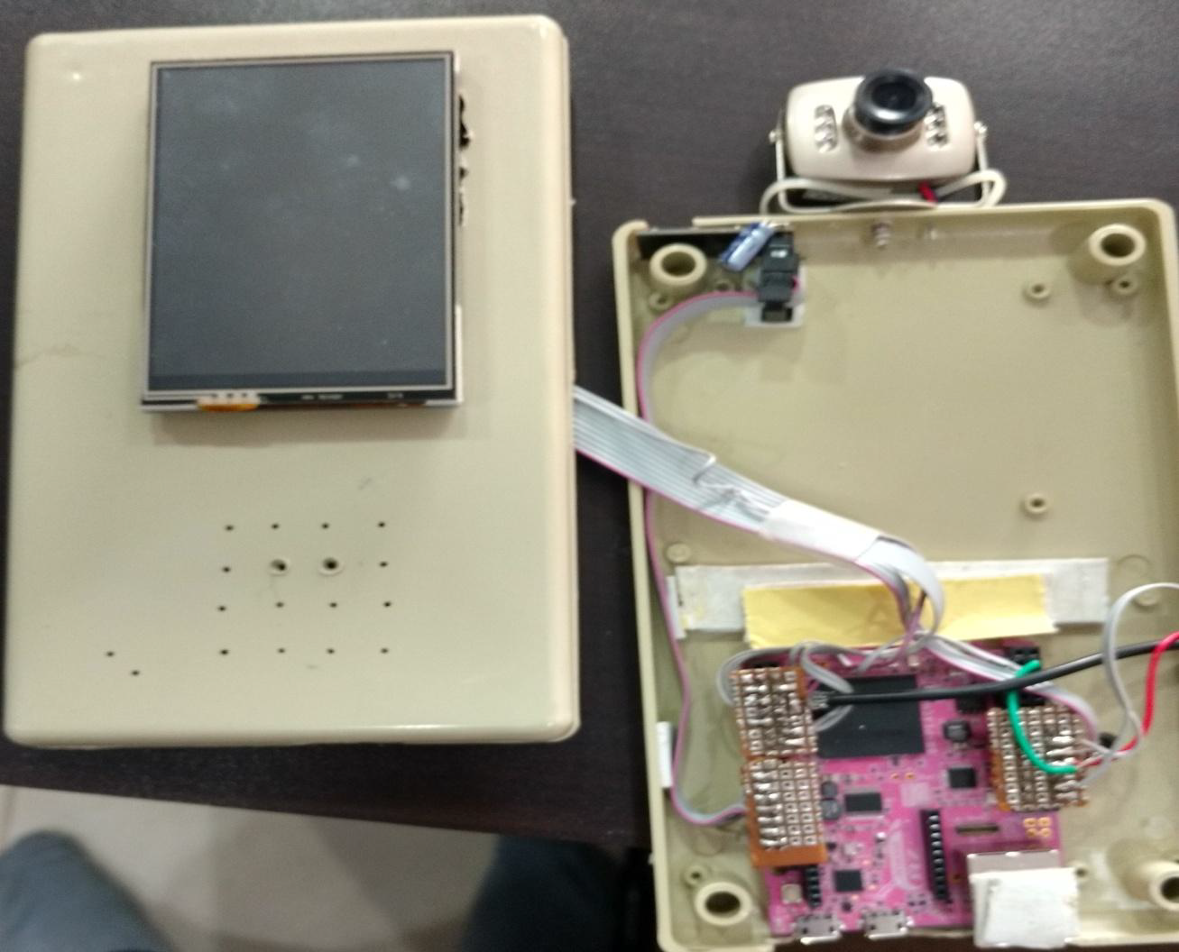
Assembly
I used a 3D printer to make a case in order to secure the paper cup and board. I have noted the STL data below but, depending on the size of the paper cup, you may not be able to use it as is. The data is based on a cup 8cm in height and 7cm in width.
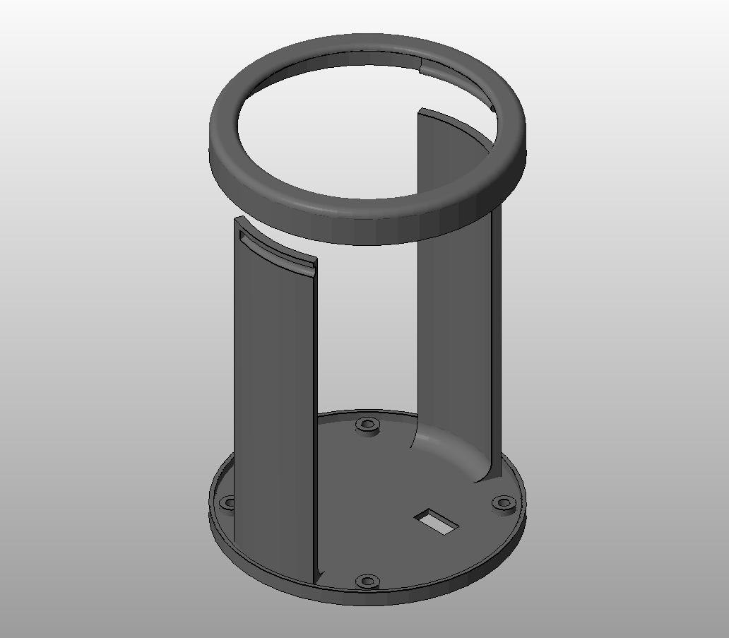
STL file (download)
Secure the base board with screws.
The power switch show pole out on the reverse side.
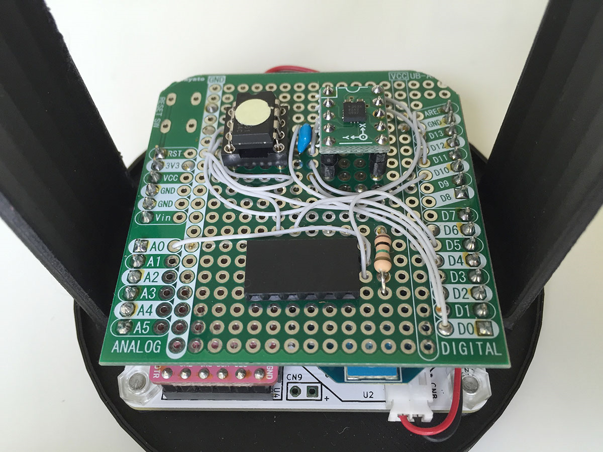
The universal board (shield) on top of the base board.
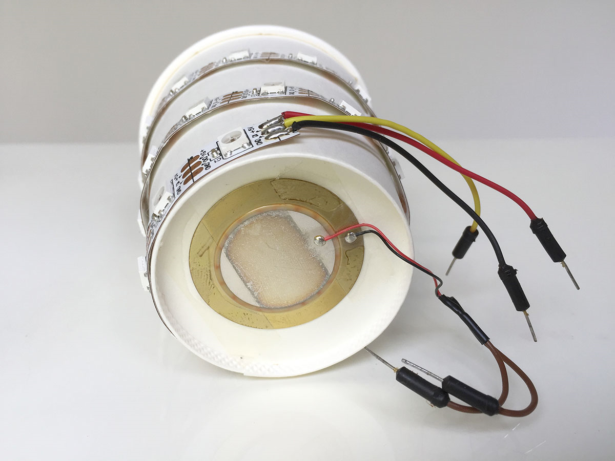
Attach the LED tape and piezo electric effect element on the paper cup and connect the jumper wires.
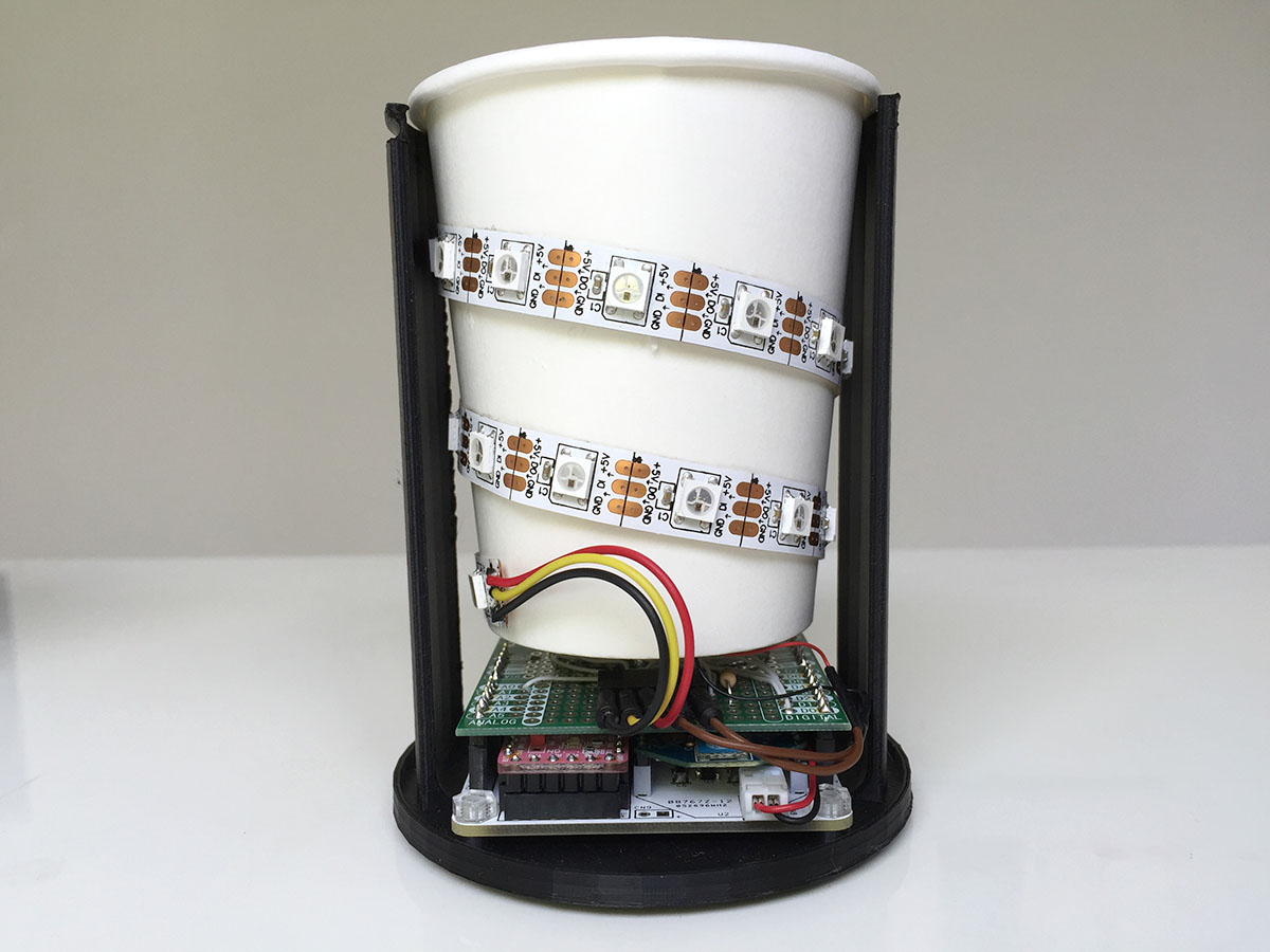
Set the cup above the universal board, connected the jumper wires, and the gadget is basically ready to go.
Flowchart
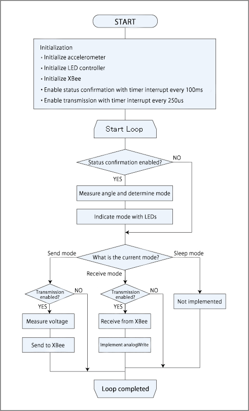
First, initialize each device. Then set timer interrupts for regular confirmation of status and SEND/RECEIVE flag alert.
The main loop switches to the corresponding processing based on flag, mode status, etc.
The timer interrupt triggers measurement of the cup angle every 100ms, to confirm the mode. Whenever the send mode is detected, voltage should be measured and data sent to XBee; and whenever the receive mode is detected, data received from XBee, PWM ouput processing should be executed every 250us for analogWrite.
Sketch
Refer here to see the sketch.
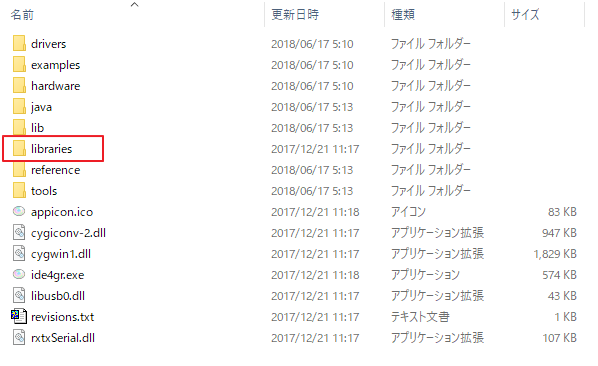
Download and implement the IDE for GR here.
http://gadget.renesas.com/ja/product/ide4gr.html
Open StringLessPhone.ino from “Open File” and write to GR-KURUMI. Correct corresponding codes if not using an accelerometer or LED controller.
The serial port is shared for computer connection and the LED controller. When the Connecting the LED controller is connected might cause the write command to fail. If so, temporarily disconnect the LED connector from the socket.
In conclusion
I was able to get the phone gadget working before the Gadget event, but, as expected, it was rather hard to hear the voice output and a real conversation was difficult. That said, I haven’t had time to fine-tune the gadget yet, so is still great room for improvement. Actually voice carried pretty will, given that no amp was used, and despite the fact that the circuitry was minimal. I see potential for application in any number of ways.
If you glance at the flowchart, you will see that there was no sleep mode when the gadget was presented at Renesas Night. What we learned then was that tilting the gadget downward would result in GR-KURUMI and XBee entering sleep mode, and that tilting the gadget upward would cause the accelerometer to interrupt the sleep mode. I haven’t figure out how to use ADXL362 quite yet, but it looks like it could result in ultra-low energy consumption. I see this as a future challenge.
Another application idea would be to have an LED turn on when a signal was received indicating the device was in sleep mode. Unfortunately, I did not have the time to try out this idea.
This creation was based on my interest in what would happen if I eliminated the “string” from a toy phone. I felt as though I were reinventing the telephone. If someone out there is interested in trying the same thing, I urge him or her not to be confined by my own framework, but to explore new ways of creating a wireless toy phone.
I like to fool around with electronic gadgets as a hobby.
I am one of the GR-SAKURA producers so most of my creations are based on Gadget boards.
http://yushakobo.jp

Follow