
Title:Smart Greenhouse Control System
Displayed Name:Miza Hilmiyah Bte Paujan
| Concept / Overview |
|---|
| The Smart Greenhouse Control System hopes to design a platform for indoor agriculture solutions of controlled environment with optimum and sustainable cultivation conditions to ensure stable and sustainable production of quality crops as well as to better utilize the limitation resources with the advancement in semiconductor technology. |
Introduction
In Singapore context, due to its small geographical size and population, land scarcity and tight labour can prove challenging for businesses especially in the area of agriculture solution providers in terms of having the required space and the manpower to operate, as well as the costs of maintaining the business operation.
The aims of the Smart Greenhouse Control System hope to design a platform for indoor agriculture solutions of controlled environment with optimum and sustainable cultivation conditions to ensure stable and sustainable production of quality crops as well as to better utilize the limitation resources with the advancement in semiconductor technology.
System Design and Description
The following depicts the hardware block diagram of the system:
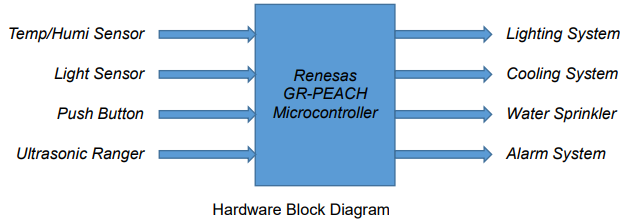
The system uses GR-PEACH mbed-RZ/A1 board as the main controller for the computation and the decisional operations. It works in complement with the ambient environment as well as the input sensors such as the light and the temperature/humidity sensors situated within the greenhouse to control the output systems such as the lighting, cooling and the water sprinkler within the greenhouse.
The light sensor is to detect the presence/absence of the sunlight during the day/night/raining day in order to control the lighting system within the greenhouse to provide a near 24 by 7 hours of daylight condition to stimulate the growth of the crops.
The temperature sensor is to detect the ambient temperature within the greenhouse in order to control the cooling system to provide a near constant temperature environment that is suitable for the growth of the crops.
The humidity sensor is to detect the ambient moisture level within the greenhouse in order to control the water sprinkler to provide a suitable level of moisture for the growth of the crops.
An alarm system using an Ultrasonic Ranger sensor for intrusion detection and a push button for arming/disarming the system.
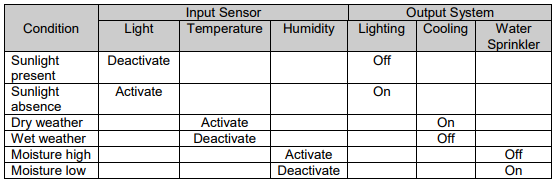
Operating Sequence of the System
The operating sequence of the system is as following:
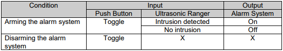
The operating sequence of the alarm system is as follow:
Component Lists
a. Light sensor
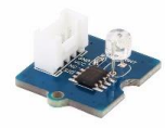
The light sensor integrates a photo-resistor; which is a light dependent resistor to detect the intensity of the light. The resistance of the photoresistor decreases when the intensity of light increases.
A dual Op Amp chip LM358 on board produces voltage corresponding to intensity of light based on the resistance value. The output signal is an analogue value in which the brighter the light, the larger is the value.
This module is use to build a light controlled switch to switch off the lighting system during the daytimes and switch it on during the night times or bad weather conditions.
b. Temperature & Humidity Sensor
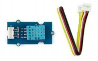
The temperature & humidity sensor provides a pre-calibrated digital output. A unique capacitive sensor element measures the relative humidity and the temperature is measure by a negative temperature coefficient thermistor. It has excellent reliability and stability.
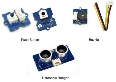
c. Ultrasonic Ranger
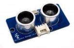
The ultrasonic sensor is a non-contact distance measurement module that works at 42 KHz for projects detection that require a middle distance measurement.
d. Push Button
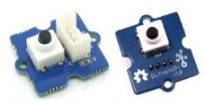
It is a momentary push button. It contains one independent “momentary on/off” button that rebounds on its own after it is release.
The button outputs a HIGH signal when pressed, and LOW when released.
e. Buzzle
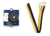
The buzzer module has a piezo buzzer as the main component. It connects to the digital outputs and emits a tone when the output is HIGH.
It can also connect to a pulse-width modulation output to generate various tones and effects.
f. Relay Module
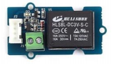
The module is a digital normally open switch. Through it, one can control circuit of high voltage with low voltage such as 5V on the controller.
There is an indicator LED on the board, which will light up when the controlled terminals close.
g. Base Shield
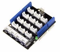
The expansion board is an Arduino compatible base shield use to interface the sensors conveniently to the GR PEACH board without connecting to the bread-board using jumper wires.
There are in total 16 connectors providing four units of analogue ports, seven units of digital ports, a unit of UART and four units of I 2C ports.
Apart from the rich connectors, there is a reset (RST) button and a green LED to indicating power status.
The base shield also provides a power toggle switch to select the suitable voltage (5V or 3.3V) of the microcontroller main board using the sensors.
Hardware Construction
a. The Greenhouse
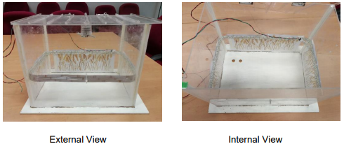
The Smart Greenhouse Control System is build using an acrylic structure to represent the greenhouse.
It is a simple structure with four transparent walls and a rooftop in which within the structure is wherein the crops are to be growth.
b. The Lighting System
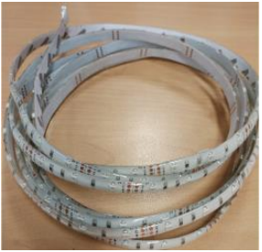
A 5V LED strip is use to simulate the lighting system within the greenhouse. The strip is connect via a relay to actuate the action.
A 5V high output voltage lights up the LED strip and a 0V low output voltage turns off the strip.
c. The Cooling System
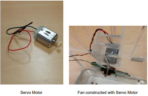
A servo-motor connects as a fan is to simulate the cooling system within the greenhouse.
Similar to the 5V LED strip, it is connect via a relay to actuate the action.
d. The Water Sprinkler
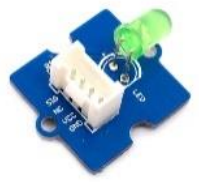
A LED is to simulate the sprinkler system.
A 5V high output voltage lights up the LED and simulates the water sprinkler is working.
A 0V low output voltage turns off the LED and simulates the water sprinkler is off.
e. The Alarm System
The alarm system is build using the ultrasonic ranger together with the buzzle. A push is use to simulate the arm/disarm mechanism of the alarm system.
As long as the alarm system is not arm by toggling with the push button, the ultrasonic ranger will not detect any object within its preset distance.
f. The Base Shield
The connection of the above sensors to the GR PEACH board is via the base shield.
The base shield sits on top of the GP PEACH board in line with the Arduino connectors provided.
The control of the sensors are using the component database hosts reusable libraries provided by the respective supplier for the different hardware.
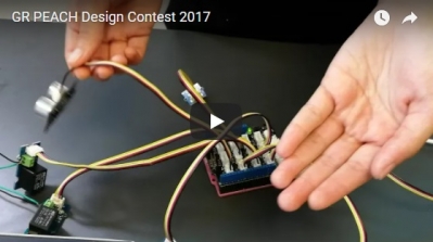
Movie
Testing Procedure & source
a. The Lighting System
During the daytime, there is plenty of sunlight and the crops within the greenhouse, with the sunlight, will grow as per normal.
When the night falls or during a cloudy or raining day, there will be low or no sunlight present within the greenhouse, the light sensor detects no light and activates the lighting system.
The lighting system is tested by physically cover up the light sensor to simulate the presence or absence of the sunlight around the greenhouse during the day or night times.
The LED strip lights up when the light sensor is cover up. Otherwise, it is off.
b. The Cooling System and The Water Sprinkler
The temperature and the humidity sensor works hand in hand.
When the temperature as well as the humidity within the greenhouse reach the pre-set values that are not suitable for the crops to grow, the fan or the cooling system together with the water sprinkler will kick in to lower the ambient temperature as well as to moist the environment.
The cooling system and the water sprinkler is tested by using a hairdryer to blow hot air to raise the temperature/humidity until the fan moves and the LED (simulate the water sprinkler) lights up.
c. The Alarm System
At the end of the day where the greenhouse is empty, the alarm system is to be armed by the simulation with the push button.
Any intruder detected within a radius of less than 0.5m to the greenhouse activates the alarm and the buzzle goes off.
Refer to the attached video for the better understanding of the testing procedure.
Conclusion
The team of ITE students, under the supervision of their lecturer, enters the competition to gain experience as well as to put their knowledge of C language programming on MCU applications of a similar 32 bits ARM core based board learnt during their course of study into real practise of designing a system.
The Smart Greenhouse Control System is by no mean a working system but merely a proof of concept of the idea of a possible system to the best of the students’ knowledge and abilities.
Finalist, GR-PEACH Design Contest 2017 in ASEAN
