
Title:Low-cost vector network analyzer - VNA for measuring the antenna of IoT devices
Displayed Name:Nguyen Manh Thao

| Concept / Overview |
|---|
| The project presents a device that analyzes qualities of the antenna in IoT devices by using the low cost embedded modules. It can be used by the IoT start-ups for developing wireless communication devices. The low cost VNA based on the principle of comparison between transmitted wave and reflected wave on the antenna to compute the reflected factor and appreciate qualities of the antenna. |
Introduction
The project presents a device that analyzes qualities of the antenna in IoT devices by using the low cost embedded modules. It can be used by the IoT start-ups for developing wireless communication devices. The low cost VNA based on the principle of comparison between transmitted wave and reflected wave on the antenna to compute the reflected factor and appreciate qualities of the antenna.
Nowadays, the IoT field is developing significantly, so the quality requirements of IoT devices is not only about the stable operation of itself but also a good ability in communicating with other IoT devices. Therefore, the demand of analyzing qualitiy of the antenna is more necessary. However, the solutions, as well as devices that analyze the quality of the antenna, are still not popular and very expensive.
To measuring the quality of antenna, the RF loss that is created by antenna will be analyzed. There are some machines/devices can do this task such as:
- Voltage Standing Wave Ratio Meter (SWR Meter or VSWR Meter)[1]
- The SWR meter or VSWR (voltage standing wave ratio) meter measures the standing wave ratio in a transmission line. The meter can be used to indicate the factor of mismatch between a transmission line and its load (usually a radio antenna), or evaluate the effectiveness of impedance matching efforts. Unless there is any reflection from the antenna in a transmission line, the standing wave ratio is 1.
- The advantage of SWR is using software to simplify the hardware and reduce cost.
- The main disadvantage of SWR is that SWR meter does not measure the actual impedance of a load (the resistance and reactance), but only the mismatch ratio.
- Scalar Network Analyzer (SNA)[2]
- SNA is a device used for characterizing or measuring the response of devices at RF or even microwave frequencies. SNA works just as a spectrum analyzer in combination with a RF generator but only measures the amplitude properties of the device under test.
- The main advantage of SNA is that the hardware required for down-conversion and power detection is relatively simple and inexpensive. In addition, because the detectors are broadband devices, it is unnecessary to re-tune the receiver to measure power at a different frequency.
- There are some disadvantages of SNA. Broadband detectors are susceptible to spurious tones and broadband noise. In addition, because the calibration is scalar in nature, it is not as accurate as full vector calibration. Due to their lack of selectivity, scalar network analyzers tend to have limited dynamic range compared to vector network analyzers.
- VNA is a basic type of network analyzers like SNA that measures both amplitude and phase properties.
- There are 2 main types of VNA:
- Normal VNA:
- Pros: Broadband, popular.
- Cons: High cost, large size.
- System on chip VNA:
- Pros: Broadband, small size (System on chip).
- Cons: Using complex VLSI technology, production expense is high, still in research.
|
|
Cost |
Size |
Frequency |
|
SWR Meter |
Medium |
Small |
Low (Under 600MHz) |
|
SNA |
Medium |
Large |
High |
|
Normal VNA |
High |
Large |
High |
|
SoC VNA |
Still in research |
Small |
High (4GHz – 32GHz) |
Table 1. Comparison of different devices
After reviewing these solutions as well as devices, our team decides to make a device having all advantages above and get rid of all disadvantages:
- Cost: Low (Under 100$)
- Size: Small (support to measure the sub-GHz antenna without influence of the floating current on the coaxial cable)
- Frequency: ISM band such as 433 MHz band, 900 MHz band, 2.4 GHz band
- Intuitive and easy to use
[1] The ARRL Antenna Book (21st ed.), The American Radio Relay League, Inc., 2007, ISBN 0-87259-987-6
[2] Introduction to Network Analyzer Measurements Fundamentals and Background - National Instruments, http://www.ni.com/rf-academy
[3] Highly Integrated 4–32-GHz Two-Port Vector Network Analyzers for Instrumentation and Biomedical Applications, Johannes Nehring, Marco Dietz, Robert Weigel
[4] Introduction to Network Analyzer Measurements Fundamentals and Background - National Instruments, http://www.ni.com/rf-academy
Target, content and plan
- Target
Research and fabricate a device that analyzes qualities of the antenna in IoT devices with the low cost, lightweight and meet the frequency band requirements. The device contains following modules:
- PLL Frequency Synthesizer: IC ADF4350 generates the RF to perform measuring.
- Directional Coupler: include 2 IC DC0873LF to separate wave into transmitted wave and reflected wave using for comparison.
- Gain and Phase Detector: IC AD8302 which receiving the transmitted wave and reflected wave for comparing show the Amplitude and the Phase of the RF.
- MCU + Transceivers: Via Analog to Digital Converter module, MCU (Renesas Peach board) receives the Amplitude and the Phase from the Gain and Phase Detector. With 2 parameters and the frequency which is generated in the PLL Frequency Synthesizer to analyze the reflected wave in the antenna. After that, the result will be shown on the LCD or other devices through Transceivers.
- Transceivers: Including of a bluetooth module and a wifi module, transceivers are responsible for showing the results to users in different ways. For nearby users, they can connect their phone to the device to see the results. For faraway users, they can see the results on website thanks to wifi module integrated on the device. This wifi module take data from MCU and send to web sever to show on the website.
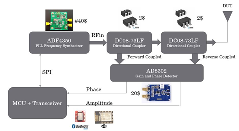
Figure 1. The block diagram of the proposed device
- Content and plan
- Content 1: Review these solutions as well as devices
Content: Review these solutions as well as devices and show its advantages and disadvantages.
Plan: Read and analyze.
Expected Result: Hardcopy report.
- Content 2: Design schematic and block diagram
Content: Base on the normal VNA and the RF modules on market, design the block diagram and the schematic.
Plan: List all necessary modules and design the block diagram and the schematic.
Expected Result: List of modules, block diagram and schematic design.
- Content 3: Programming libraries for the MCU to communicate with other modules, layout PCB
Content: Programming libraries for the MCU to communicate with other modules, layout PCB as the same time.
Plan: Programming and layout PCB.
Expected Result: Libraries and PCB.
- Content 4: Connecting modules
Content: Follow the schematic to connect modules.
Expected Result: Completed device.
Movie
A device that analyzes qualities of the antenna in IoT devices with small size, low cost and meet the frequency requirements.
Link for source
Source folder: https://drive.google.com/open?id=0B04fVTf-NT0DU3ZtdEViNTlVM0E
Mbed reposistory: https://os.mbed.com/users/nguyenmanhthao996tn/code/VNA_RenesasGRPeach/
Finalist, GR-PEACH Design Contest 2017 in ASEAN
