Title:Autonomous Robot for Indoor Surveillance and Monitoring
Displayed Name:Nguyen Trong Nghia
| Concept / Overview |
|---|
| The robot will have three main features: it can locate its position and run across the building, it will gather sensor data from the area that it passes through, and it is able to process that data and send only crucial or abnormal information to the cloud which can only be accessed by the administrator. |
General Ideas
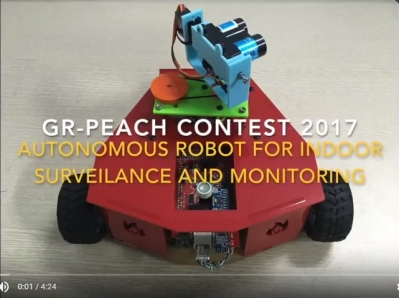
Safety and security are two most concerned aspects in offices and factories. At such places, it's crucial to make sure that there is no intruder, or unwanted behavior to happen. Currently, security system consists of a bunch of cameras in every corner of the building, a sensor hub to monitor temperature, gas, motion, and some security guards to watch the cameras and sensor status. This setup has been applied for many large buildings and factories. However, lots of accidents and break-in still exist because of human mistakes. Specifically, guards are usually getting bored of their repeated jobs, and omit some steps in securing the building which leads to security hole. In additions, monitoring lots of cameras and sensors is a difficult job, especially when it lasts for hours at midnight.
For this reason, we want to build an autonomous mobile robot platform to solve this problem. The robot will have three main features: it can locate its position and run across the building, it will gather sensor data from the area that it passes through, and it is able to process that data and send only crucial or abnormal information to the cloud which can only be accessed by the administrator.
An autonomous mobile platform will in form of 3-wheel rover.
An autonomous robot system composed of three main problems: navigation, planning and path following. In this paper, we proposed a completely autonomous vehicle for indoor surveillance and monitoring. Firstly, the robot needs to know its current position. For outdoor environment, GPS-based location is very popular and widely used because it’s simple to use and provide reasonable accuracy. However, its accuracy is only about 5 meters, and it is not applicable for indoor environment, where the building structure blocks the line-of-sight signal from the satellite. Also, commercial indoor localization systems currently using beacon, RSSI, or ultra-wide band to figure out the object position. Their advantages are easy to implement and relatively
cheap, but the biggest drawback is their accuracy – only reach about 1 meter. Therefore, those systems cannot be applied for motion planning and vehicle guidance tasks since they require higher level of accuracy to drive the vehicle in small spaces with less error.
In this project, we have established a novel indoor positioning system using ultrasonic and RF signal with higher accuracy (about 5cm) and fast refresh rate (40Hz). Additionally, a mobile vehicle, which we named PEACH-CAR, is powered by Renesas GR-PEACH board and can run autonomously on the designed path to monitor environment and stream camera to the user
though the Internet. To make it possible, the robot runs Mbed-based Real-time Operation System, with threading and multitask scheduling.
System Description
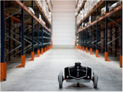
Figure 1. Robot system setup for localization and tracking
The proposed positioning system has two parts: a mobile part and stationary part. The mobile part is PEACH-CAR, a rover that carries ultrasonic & RF transmitter. In contrast, the stationary part includes a CAN network in which a coordinator and ultrasonic receiver nodes communicate to each other. The coordinates of the moving target are determined and stored in
a PC, which acts as a server. The distances from the transmitter to all receiver nodes are transferred from the coordinator to the PC via a serial connection. The system structure is illustrated in Figure 1.
This system has an accuracy in the centimeter range, can be extended and is feasibly for reallife applications. The CAN network has many advantages, which are perfectly suitable with our setup.
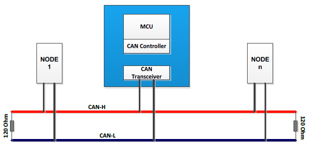
Figure 2: CAN bus for sensor node management
In our proposed system, the RF signal is used for time synchronization between the transmitter and all receiver nodes in distance measurements using TDoA. However, applying each RF transceiver unit to each receiver node is not a very effective way in terms of network management, system complexity and scalability. As all receiver nodes in ultrasound-based indoor
localization are attached at pre-defined points and require power for operation, the CAN network can be established by adding two more wires to the power bus to replace the RF protocol in synchronization and management between the coordinator and all receiver nodes.
Similar to many other industrial wired protocols, the signals on the CAN bus is differential, which allows CAN to acquire its robust immunity to noise and fault tolerance. Differential signaling reduces the electromagnetic noise and allows a faster data rate over a twisted-pair cable. In particular, CAN uses a bit-wise arbitration mechanism to solve the collision problem.
The Identification (ID) field of CAN message can represent both device information and message priority. The highest priority ID message always wins the bus access and keeps on transmitting when two or more devices start transmitting their message at the same time.
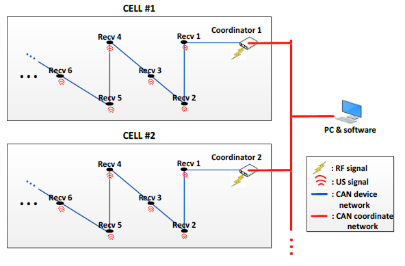
Figure 3: System setup for extendable sensor network
Autonomous Vehicle System
A mobile vehicle is powered by Renesas GR-PEACH board, which is a powerful microcontroller and supports several advanced peripherals. This board enable signal chip solution for our application. The PEACH-CAR runs Mbed RTOS to enable multitask operation.
The following figure describes the robot model operation. Firstly, the car gathers lots of sensor data, such as gas sensor, fire sensor, temperature, humidity, light intensity, and sound level in order to understand its surrounding environment. Since different sensors have different update interval, task scheduling and callback functions are designed to handle this difficulty, and also solve the problem of sensor hanging or failure that cause the whole system crash. Secondly, to obtain indoor positioning information from the internet as well as stream video from camera to the internet, we have implemented RTOS to handle network operation, video stream, and HTTP server for video streaming. Thirdly, after the robot has known its current position, it drives two motors with PID controller to guide the vehicle follow the designed path, sent from the planner software. The biggest challenge that we have walked through is how to ensure these three functions work smoothly together.
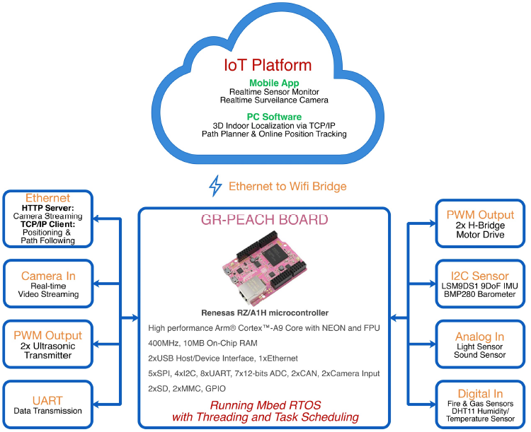
Figure 4: PEACH-CAR robot system powered by GR-PEACH
Hardware Structure
Ultrasonic Transmitter
The ultrasonic transmitter is mounted on the robot model, and periodically emits ultrasonic signal. The receiver nodes will then receive the ultrasonic signal, and calculate distance from the robot to each sensor node using Time Delay of Interval algorithm. After obtained the distance, the data is sent to PC via Bluetooth to estimate 3D position of the robot model. Nonlinear Lest Square algorithm is implement to further reduce positioning error from the sensors.
An ultrasonic drive consists of a Quadruple Half-H Driver SN754410, it converts PWM signal from GR-PEACH to 12Vpeak-peak signal that drives an ultrasonic transmitter. This setup is designed to maximize transmitting power, that leads to the increase in maximum travel distance.
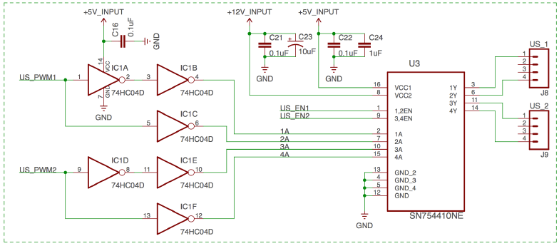
Figure 5: Ultrasonic transmitter driver circuit
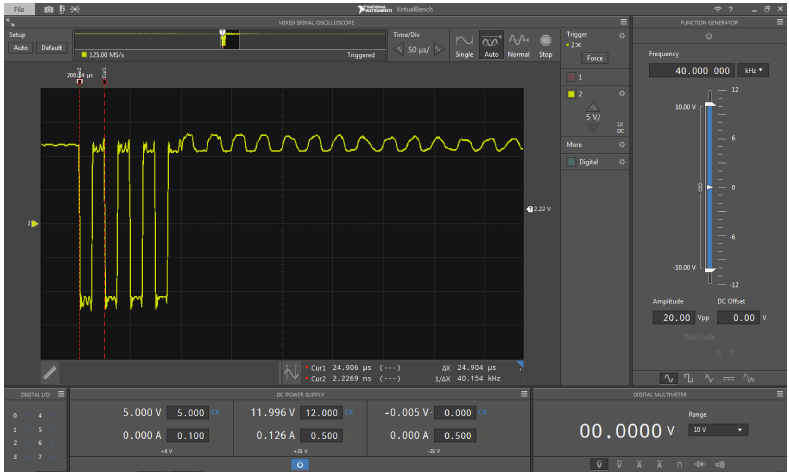
Figure 6: Output signal of ultrasonic driver
Ultrasonic receiver
Each receiver node as an ultrasonic amplifier to increase the received ultrasonic signal. However, the ciccuit noise is also increase along with the desire signal. To address this issure, our team has design a band-pass filter and amplifier circuit, which not only amplified the received signal by 330 times, but also only allows signals with central frequency of 40Khz pass through. This design has greatly enhanced the distance measurement accuracy and also eliminate DC noise from the output.
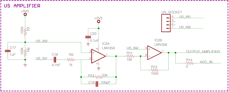
Figure 7: Ultrasonic amplifier and band-pass filter circuit
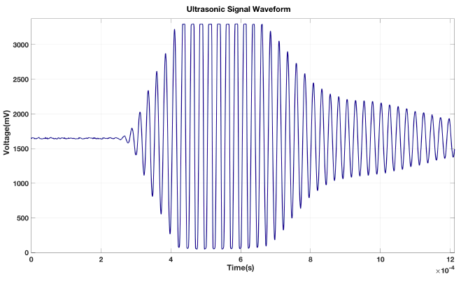
Figure 8: Output signal of ultrasonic receiver
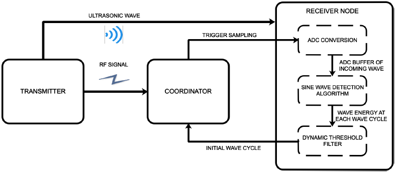
Figure 9: Block diagram of the processing sequence in the receiver node.
Internet-of-Things infrastructure
To enable wireless connection to the Internet for GR-PEACH, we use Beaglebone board as Wifi bridge. First, Beaglebone establishes WIFI to Ethernet bridge (with DHCP server) to enable Internet acess for GR-PEACH. Moreover, Beaglebone acts as a mini computer to received sensors data from GR-PEACH and upload to Blynk Cloud via software API. After the sensors information is available in the website, clients can access them through website and mobile Blynk-based application. This is a standard system model for current IoT system.
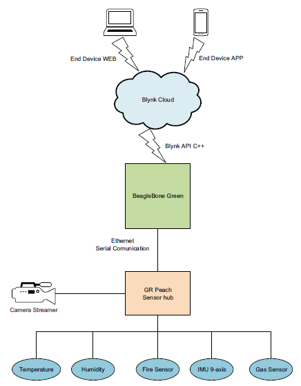
Figure 10: Flow chart of IoT infrastructure for GP-PEACH
Firmware & Software Development
Firmware
As mentioned in system structure, GR-PEACH runs Mbed RTOS with threading and task scheduling to gather sensor information, stream camera, receive localization information and control motors speed to drive the robot model follow the establish path. All tasks must runs simultaneously without corruption, and the firmware structure is described in the flow chart below.

Figure 11: Flowchart of GR-PEACH firmware structure
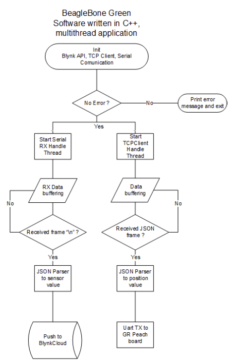
Figure 12: Flowchart of Beaglebone software structure
Software
3D Indoor localization software
The software connects to the sensor network coordinator via Bluetooth to gather distance measurement data from 5 receivers, then calculate robot position using Nonlinear least square algorithm and display the result on the screen.
The software also establishes TCP/IP Server so that clients can access and obtain positioning data for applications that require positioning information.
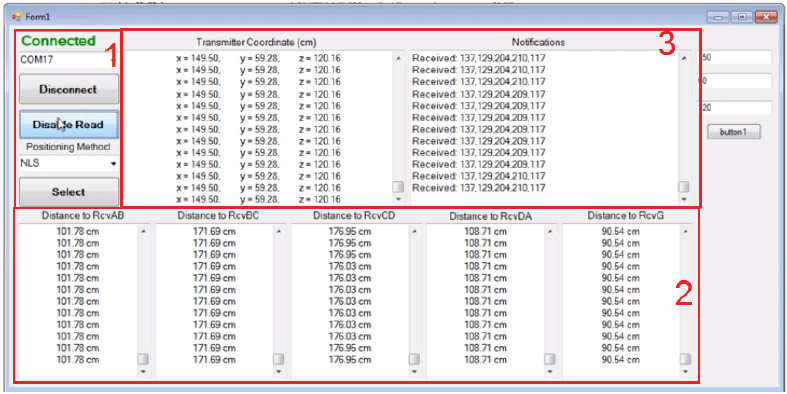
Figure 13: 3D Indoor localization software
- 1: Manage connection and choose positioning algorithm to calculate object position
- 2: Display distances from a moving vehicle to each corresponding receiver nodes
- 3: Display 3D positioning results of the object using the selected method
3D Path Graphing Software
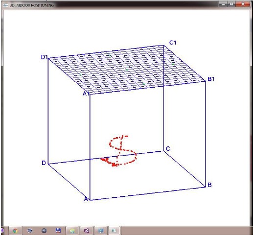
Figure 14: 3D Path Graphing Software
• Receive 3D position from TCP/IP server, use OpenGL library to draw 3D travel path in realtime.
• Capable of changing point of view to better observe and evaluate driving path and positioning accuracy.
Vehicle Path Planner Software
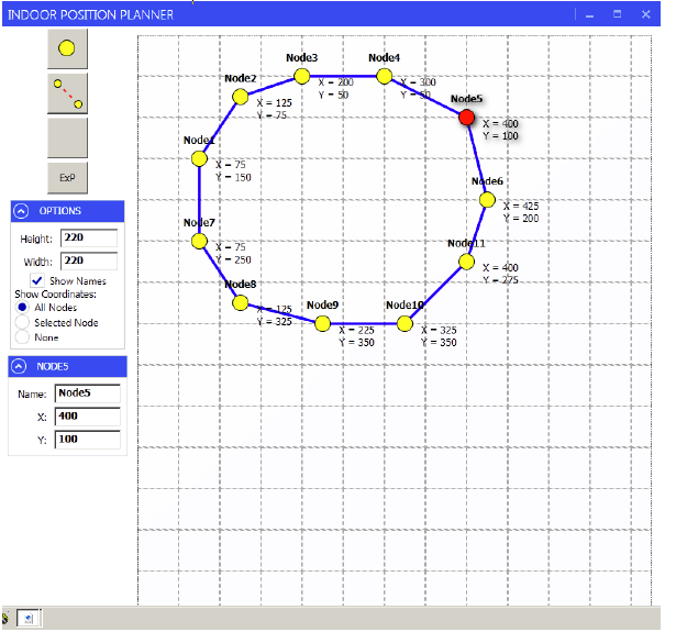
Figure 15: Vehicle Path Planner Software
• Graphical 2D interface allows use to choose multiple destination and establish path for surveillance robot.
• Have an ability to create node, click and drag move, establish path between nodes, and published desired map for path following application.
Blynk-based IoT Mobile App for Real-time Monitoring
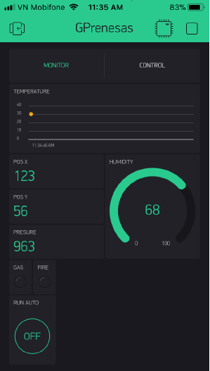
Figure 16: Mobile App for realtime sensor monitor
• Use Blynk cloud service to create app in 2 mobile platforms, Android/ iOS, allow monitoring surrounding environment information, such as temperature, humidity, gasconcentration, and fire detection.
• Sensor data read by GR-PEACH is pushed to Blynk server via API and enable realtime monitoring and control.
Movie
Code
Finalist, GR-PEACH Design Contest 2017 in ASEAN
