
Title:Tracking (Color Detection) Robot with GR-LYCHEE
Displayed Name:Yuuichi Akagawa
| Concept / Overview |
|---|
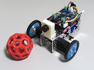
| This gadget is a robot that detects and tracks a red object. I built the system for the GR-LYCHEE Producers Meeting (Renesas Night 11). As the robot tracks a red object, it transmits the motion image taken by its camera to a smartphone or tablet for real-time viewing. GR-LYCHEE comes standard with the camera and its OpenCV library can perform the various image processing. GR-LYCHEE is also equipped with ESP32, enabling wireless communications via WiFi/Bluetooth. *The system was developed with GR-LYCHEE trial version Rev.2. Some modifications are required when using the product version. |
Mechanism
1) Imaging
In this example, objects are recognized using connected-component labeling rather than machine learning. The input image of the labeling processing must be binary image data (black and white). During this operation, the specified color is extracted. This gadget is set to process red, but since images acquired by the GR-LYCHEE camera are in YUV422 format, they can be processed as is for color gamut selection.
The YUV color space is often used for video signal applications in the following manner: Y: luminance (brightness), U: blue deviation, V: red deviation. The following graphs show the positions of U and V when plotted on Y-planes.
| Y=0 | Y=64 | Y=128 | Y=255 |
|---|---|---|---|
 |
 |
 |
 |
Since the upper left regions are defined for red, we can use the cordinates as red. But when luminance (Y) is high, the color turns from red to orange and yellow. So the Y also needs to be restricted to a certain degree. The binary image is generated using white for areas where the color is detected, and black all other areas. Then I use this binary image as input for processing the connected-component labeling.
Although OpenCV3 processes the labeling with cv::connectedComponentsWithStats(), it does not have a function for ignoring areas smaller than the specified size or sorting areas in order of size. And the GR-LYCHEE on-board memory might also be too small. Therefore, I used Labeling Class Labeling.h offered by Imura Laboratory.
I configured the tracking program as follows. The robot moves toward the largest area if mutiple areas are detected. And the robot stops if no red area is detected in the captured images.
If this is a commercial communication robot, it might move around to find the target object, but since I am developing this at my desk, I needed to avoid any risk of it falling or running away.
This sample gadget is not equipped with a distance sensor, so the robot determines when to stop based on the size of the detected red area. When the area exceeds a certain size, the robot judges it is close enough.
2) Detection result examples
| Original Image | Y | U | V | Binary image | detected result (red frame) |
|---|---|---|---|---|---|
 |
 |
 |
 |
 |
 |
 |
 |
 |
 |
 |
 |
 |
 |
 |
 |
 |
 |
The second image is a misdetection example of the robot selecting an orange color. The robot selects the wrong object even in the white ambient lighting if the target is too far and a big orange object is near it. We can use the tight values to avoid orange colors. But the robot will not be able to detect red objects either. The settings have to be fairly flexible.
3) Direction control
The direction control is rather straightforward. The robot compares the amount of space (width) on the left and right sides of the detection area and, if the space on the left side is wider, it runs the left-side motor. If the space on the right side is wider, it runs the right-side motor. Both motors are run only when the spaces on both sides are about the same width. Otherwise, the robot turns only one side motor on without any speed controls; the robot moves like a turtle.
 |
 |
| Left-side space is wider so left motor runs (robot turns to the right) |
Right-side space is wider so right motor runs (robot turns to the left) |
Configuration
1) Block diagram

All WiFi and HTTP processing is carried out by the ESP32. All other processes are handled by GR-LYCHEE’s embedded MCU (RZ/AILU), including:
- Camera image acquisition
- Imaging
- Motor control
* RA/A1LU and ESP32 communicate via UART.
2) About software operations
In order to perform the ESP32 UART transmission process and the motor driver I2C command process asynchronously, I used a method that invokes each task separately and sends messages via queues. In this way, the main task focuses on handling the image processing.
In addition, a WiFi processing of ESP32 stalls and blocks the UART data transfer. Therefore, ESP32 and GR-LYCHEE are both configured to have a double buffer so that if there is an unprocessed buffer, the write process will be disabled. As a result, some frames are lost in the moving picture although the driving control remains intact.
The core functions of OpenCV can be used with GR-LYCHEE. The red frame shown in the detection result image is also drawn by OpenCV. Since GR-LYCHEE’s camera capture and JPEG conversion functions are in YUV422 format, OpenCV functions require color space conversion (such as BGR888). Unfortunately, OpenCV does not include a function to convert BGR888 back to YUV422, so I had to add this in advance.
For more details, refer to the source code here.
3) Power source
Connect a 7.4 Li-Po battery to the motor driver and supply the 5V regulator output from the motor driver board to the Arduino 5V pin on GR-LYCHEE. You don’t need to connect power supply to the USB port.
Component List & Necessary tools
Component list
*Information as of July 1, 2017. Some items may no longer be available. Please check here for updated information.
| Part | QTY | Purchasing info (for reference only) |
| GR-LYCHEE with camara module | 1 | |
| Actobitty 2-wheel Robot kit | 1 | Akizuki Denshi Tsusho K-08456 |
| Grove I2C motor driver module | 1 | Akizuki Denshi Tsusho M-09278 |
| I2C-bus bidirectional voltage level conversion module (FXMA2102) | 1 | Akizuki Denshi Tsusho M-05825 |
| Pin header 1x40 | 1 | Akizuki Denshi Tsusho C-00167 |
| Carbon resistor 4.7kΩ(1/6W) | 2 | Akizuki Denshi Tsusho R-16472 *Purchase just 2 pieces if you can. |
| Arduino vanilla shield ver.2 | 1 | Switch Science SSCI-PCB-NVLBK |
| FFC cable(0.5/24P)150mm | 1 | Sengoku Densyo 5BWT-PPHD |
| JST-EH housing 4P | 1 | Sengoku Densyo EEHD-4KBL |
| JST-EH board posts (4P, straight) | 1 | Sengoku Densyo EEHD-4KBR |
| JST-EH contacts (5 pcs per set) | 1 | Sengoku Densyo EEHD-4P7K |
| EP air connector with 18G wire (90mm) (A male) | 1 | Eagle Model 5513 |
| EP air connector with 18G wire (90mm) (A male) | 1 | Eagle Model 3460-18AWG |
| Top racing 2P connector (1 male, 1 female) | 1 | Eagle Model 2709LP-BK when using a standard battery |
| Heat resistant electronic wire | AWG28 or the equivalent | |
| Solder | ||
| M3x6 screw | 1 | |
| M2x10 screw | 4 | |
| M2 nut | 4 | |
| Seismic mat 4×4cm | 1 | Normally available at hobby shops or similar inexpensive DIY shops. |
| Magic band 10mm width | Linkman BTYPE1.5M |
Use a 3D printer to make the following items.
| Part | QTY | STL |
| Camera mount | 1 | Download |
| Spacer for motor driver mode (inner diameter: 2mm x 5mm) | 4 | Downlaod |
Required Tools
- Soldering iron
- Phillips head (plus) screwdriver
- Flathead (minus) screwdriver
- Pliers
- Nippers
- Wire stripper
- Pin vice
- 2mm drill
- 2.4mm drill
- Tap handle
- M3 tap
- Crimping pliers
- 3D printer
How to make the robot chassis
1) Assembing Chassis
I used the Actobitty 2 wheel Robot kit for the chassis. It comes ready for the Arduino UNO attachment.
The kit includes a 90rpm geared motor which runs very slowly and requires a power source of 6V to 12V.
*My tracking robot uses a 7.4V Li-Po battery.
The kit is easy to use and doesn’t require any special modifications. Just follow the instructions in the Assembly Guide. The motor connector is unnecessary so just remove it and remove the coating.

2) Make the camera mount
Download the STL here and generate the mount with your 3D printer. (layer pitch: 0.2mm or less)
After the block is output, use a 2.5mm drill to open a hole on the bottom surface, then thread the hole with the M3 tap.


First, remove the lens from the camera module and connect the cable.
Use the 150mm cable purchased separately, not the cable that came bundled with GR-LYCHEE.

Pull the cable through the bottom of the camera mount, and then push it into the camera module.


Remount the lens back. The camera module is ready to go!

Fix the camera mount to the chassis with the 3x6mm screw.


3) Motor Driver
The PWM pin positions on the Arduino motor shield do not match with GR-LYCHEE so I selected an I2C version of the motor driver.
When using DRV8830, you will need to use two of them and the drive power may not be strong enough for this chassis. So I used Grove I2C Motor Driver board equipped with L298. But this module is a 5V operation. I had to use FXMA2102, an I2C voltage level convertor, to connect GR-LYCHEE.


Wire the FXMA2102 level conversion module on the vanilla shield.


Make holes to attach the motor driver board. Use the 2mm drill to widen the through holes at the 4 positions shown below.
It is easier to solder the pin headers to the shield after widening the holes.

Attach the shield to the motor driver board. For each hole, insert the 2x10mm screw from the backside of the shield, add the spacer, then fix the motor driver board after the spacer using a 2mm nut.
*Spacer: Print out 4 spacers using a 3D printer ahead of time.


Cut the Grove cable to the appropriate length and attach the JST PH connector. If you don’t have crimping pliers, it might be easier just to solder the cable directly to the board.


Connect the cables to complete the configuration.

4) Mount GR-LYCHEE on the chassis
Attach GR-LYCHEE to the chassis and connect the camera cables.

Next, set the motor drive shield on GR-LYCHEE.

Connect the motors; secure by tightening the screws on the terminal blocks.


Connect the battery connector; secure by tightening the screws on the terminal block.
*I used a radio control connector for this gadget, but the standard connector works just as well.

5) Mount the battery
Cut the 40x40mm seismic mat in half, and attach it to the battery.

Take advantage of the adhesive characteristic of the seismic mat to attach the battery to the chassis.

Finally, secure the battery using a Velcro band as shown in the photo.


Write the program to the MCU.
1) Preparation
Set the motor driver module as indicated below.
| Dip switch | Set all 4 to ON (same as factory setting) |
| J4 jumper | Remove when writing |

2) Write the ESP32 program
Download the program from esp32-DisplayApp-WebServer and refer to the README.md file for instructions.
3) Write the program to GR-LYCHEE.
Download this file and write it to GR-LYCHEE.
4) Operational preparation
After writing the program, remove the USB cable from GR-LYCHEE and connect the J4 jumper.

How to use the robot
To avoid malfunctions, motor control and image transmit processing are stopped immediately after startup.
The roles of each LED and switch are as follows:
| LED/SW | Description |
| US0 | Motor ON/OFF control |
| US1 | Image transmission ON/OFF |
| LED1 (green) | Initialization complete/in process |
| LED2 (yellow) | Motor control status |
| LED3 (orange) | Image transmission status |
| LED4 (red) | Object detected |
1) Power-on procedure
1-1) Connect the battery.
1-2) Reset motor driver (confirm that J4 jumper is connected)

1-3) GR-LYCHEE reset --> after a few seconds, LED1 (green) turns on.


1-4) Hold a red object in front of the camera to confirm that LED4 (red) turns on.
1-5) Press US0 to enable motor controls; LED2 (yellow) turns on. The robot is now ready to track any red object.
2) WiFi connection procedure
ESP32 operates the WiFi access point and is connected via your smartphone or tablet.
*SSID: GR-LYCHEE (6 lower digits of MAC address)
Pressing US1 enables image transfer and turns LED3 (orange) on. View the camera images by accessing 192.168.4.1 from your browser.
3) Other
There is no power switch for this robot. To turn off, simply detach the battery. Note that it is dangerous to allow the Li-Po battery to go lower than the minimum voltage.
Demo Video
Electronic gadgets and programming are my hobby.
I like to create things that will interest a few gadget maniacs, rather than the masses!
