Title:Wristwatch using GR-KURUMI
Displayed Name:@takjn
| Concept / Overview |
|---|
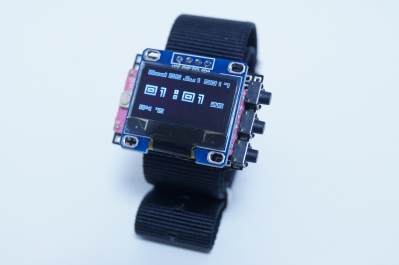
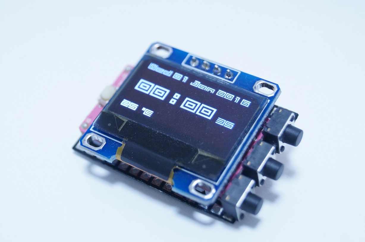
| My concept about this gadget is “to have a Renesas gadget with me every day.” I decided to create a wristwatch taking advantage of GR-KURUMI, which boasts low power dissipation and has an embedded RTC. Normally, the watch’s screen turns off and stays in the sleep mode. In this way, the watch enables low power consumption. When any button on the watch is pushed, the watch wakes up and shows the current time on the screen. The watch employs a CR2032 button battery which enables the watch to operate for 2 to 3 months. This watch has just one function – displaying the current time - and no calendar or alarm. But I have published the source code so that you can upgrade the features of the watch as you like. |
Introduction
GR-KURUMI is the smallest board available for Renesas gadgets. It is a high-performance and rather cute board, but the fact that it has no USB port for direct connection with PC or Mac limits its potential usage, making it difficult for first-timers to design it into electronic gadgets. I recommend new users to practice with GR-COTTON and GR-SAKURA before advancing to projects based on GR-KURUMI.
This system can also be made using a breadboard. For small gadgets such as the wristwatch shown in the top photo, I would recommend developing the system on a breadboard in advance, allowing you to check operations easily.
A 5V/3.3V selectable USB serial adapter must be used to write the program. Set the VCC to 3.3V. An adapter set to 5V may damage the OLED.
IDE4GR is used to write the program. Check the GR-KURUMI website to learn about IDE4GR installation and writing a code to GR-KURUMI.
Schematic Diagram Component List
Schematic Diagram
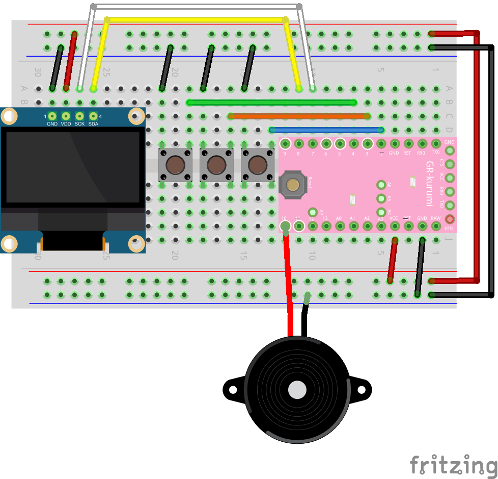
Component List
| Name | # | Description |
|---|---|---|
| GR-KURUMI | 1 | Solder the pin headers into the through holes on the long side of the board. |
| 0.96-inch SSD1306 I2C OLED module | 1 | These can be purchased through aitendo or Amazon. The module is available in blue and white, and both have the same functions; chose whichever color you prefer. The pin arrangement differs depending on the manufacturer, so carefully confirm the pin locations and the circuit diagram when wiring. |
| Tact switch | 3 | 2-leg vertical version recommended |
| Electronic buzzer (optional) | 1 | 3V buzzer is used but can be eliminated without affecting watch functions. |
Supplement
If you choose to skip the prototyping step with a breadboard, but make a small watch as shown in the top photo, be sure to take careful note of the following points:
In addition to the above components, you will need a universal board and a low-profile socket. Please purchase the necessary additional parts after reading the “How to Make a Wristwatch” section below.
- Do not solder a pin header to the ports reserved for USB serial adapter connection (short side of board with 6-pin through holes).
- To save power, cut P1 to disable the power LED on GR-KURUMI.
- Use vertical tact switches.
- Use a surface-mounted electronic buzzer.
- Any power source of approximately 3V is acceptable. The watch made here uses a CR2032 with a lead wire.
Breadboard prototyping
(1) Hardware preparation
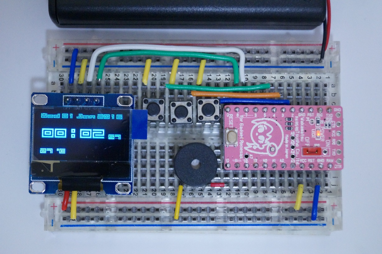
Using the schematic diagram and photo as a reference, position the wiring and parts on the breadboard. Cut the longer jumper wire to the appropriate length needed for wiring. Ensure that pin JP8 (red component) is in the OFF position.
When wiring is completed, connect GR-KURUMI to the PC with the USB serial adapter. Make sure the adapter VCC is set to 3.3V
(2) Software preparation
Download the following program, unzip, and save into a folder on your PC.
https://github.com/takjn/KurumiWatch/archive/master.zip
Invoke IDE4GR and open KurumiWatch.ino in the KurumiWatch folder. Select Tool > Board: GR-KURUMI, set the appropriate serial port, and press the “write to MCU board” button to write the program to GR-KURUMI.
(3) Confirm operations
The program will begin to execute automatically once program writing is completed. Press the tact switch connected to pin 2 on GR-KURUMI (button furthest to the right in photo). The watch will wake up from sleep mode and display the current time. When pressing the center button, the tact switch connected to pin 3 on GR-KURUMI, the display goes to the time adjustment menu, allowing you to adjust the current time.
If the device does not display the time when you press the switch, press the reset button on GR-KURUMI. Also confirm that the OLED module power is connected to the power supply. OLED port configuration will vary according to each manufacturer, so the wiring suggested here may not be appropriate.
Assemble the Wristwatch
Outline
Wiring
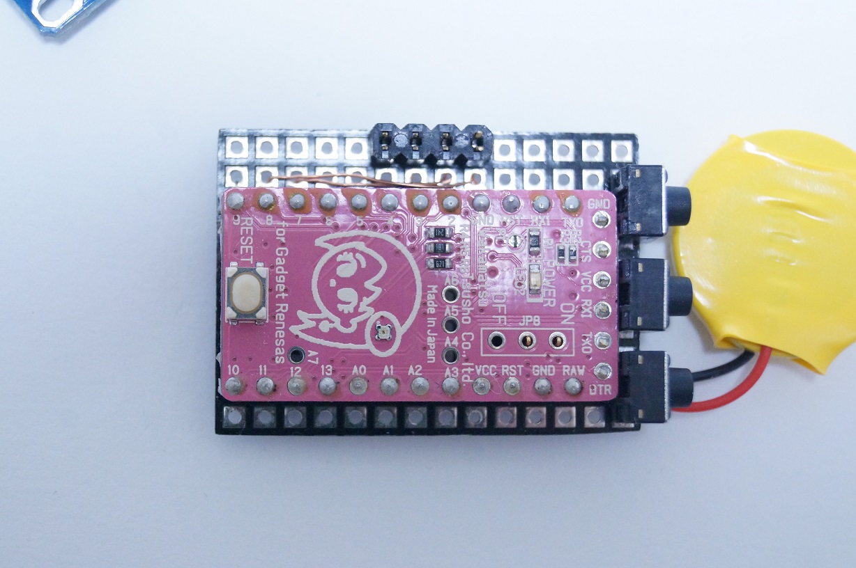
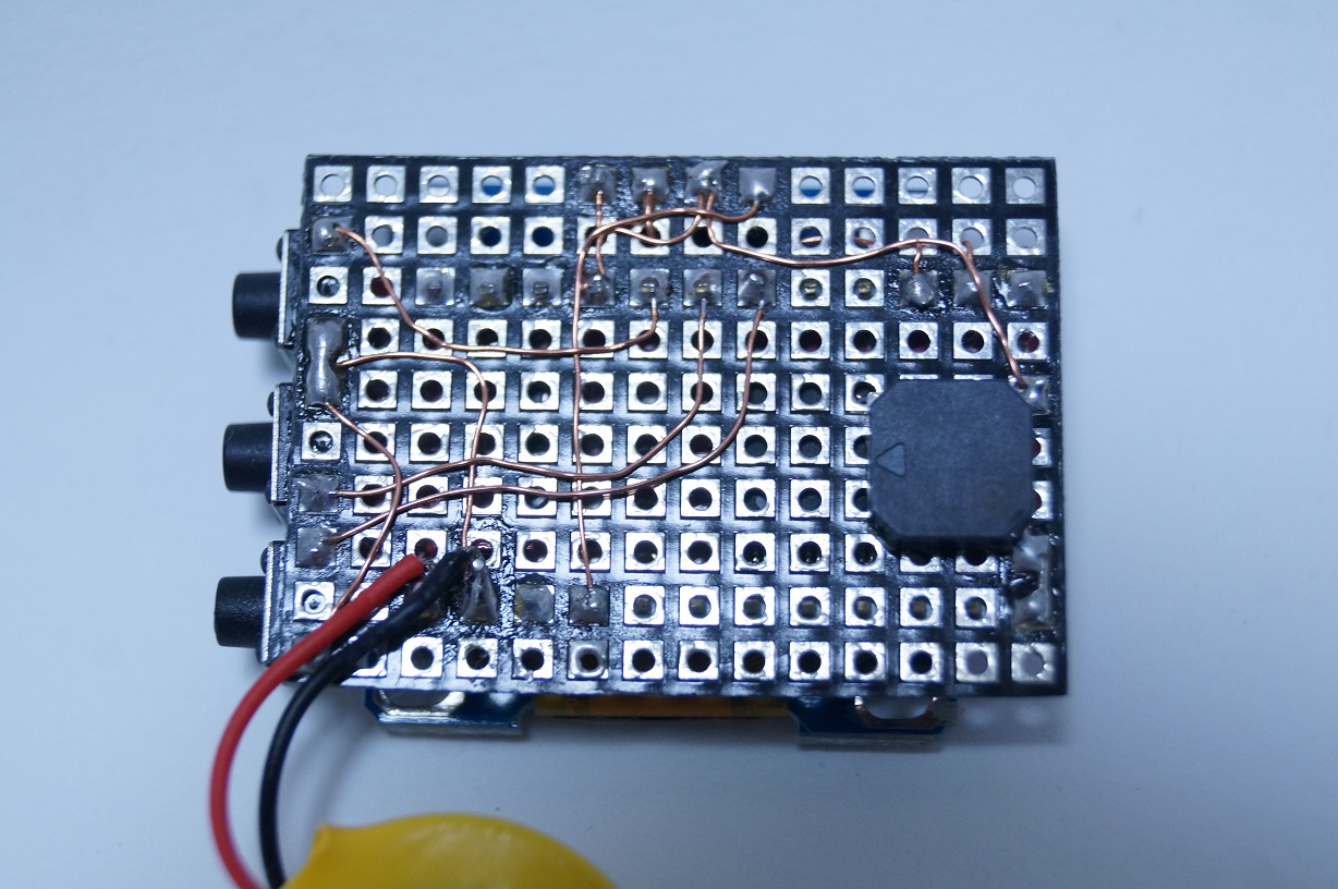
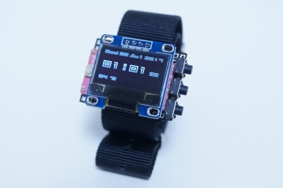
Configure the parts on the universal board and wire parts as shown in the schematics. For the wristwatch described here, I used scissors to cut an ultrathin (0.3mm) universal board purchased from Akizuki-denshi. I cut and soldered parts such as header pins which protruded too high above the exterior, as necessary. Glue parts such as the electronic buzzer to the board to make soldering easier.
Securing the OLED
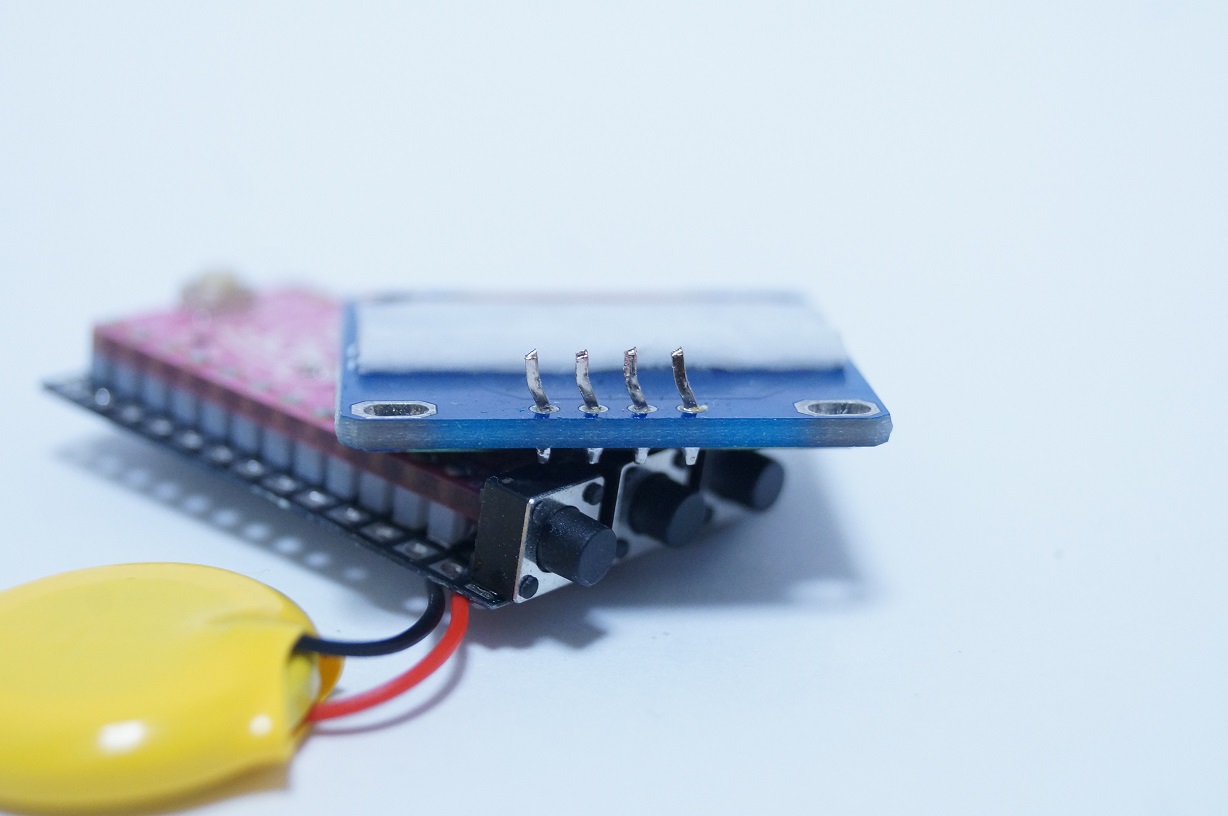
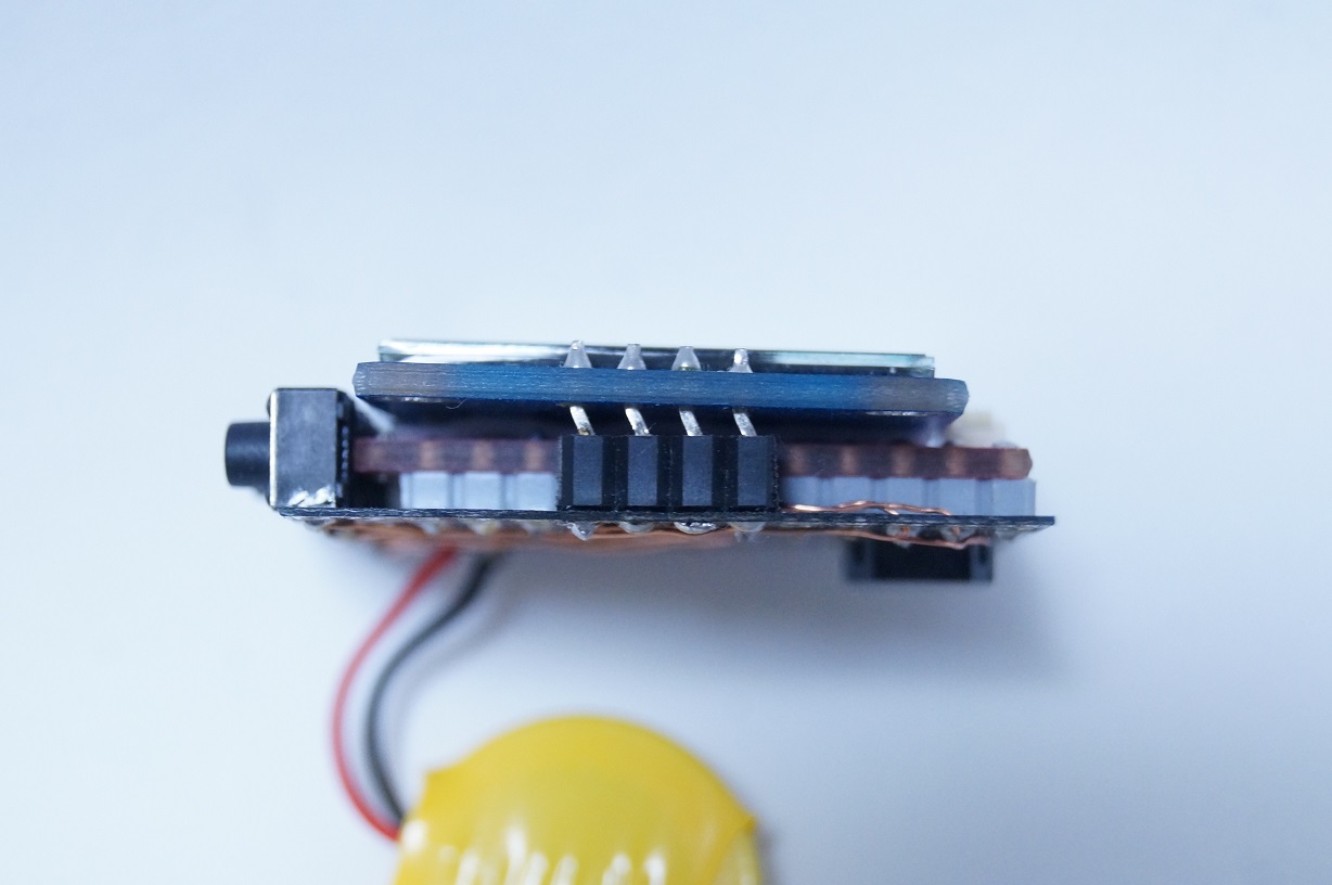
I bent the OLED pins a little and cut the tips to make the wiring look better. Then I connected the OLED to the board using a low-profile pin socket, so that it is removable. I used thick double-sided tape to secure and insulate the OLED and GR-KURUMI.
Securing the strap
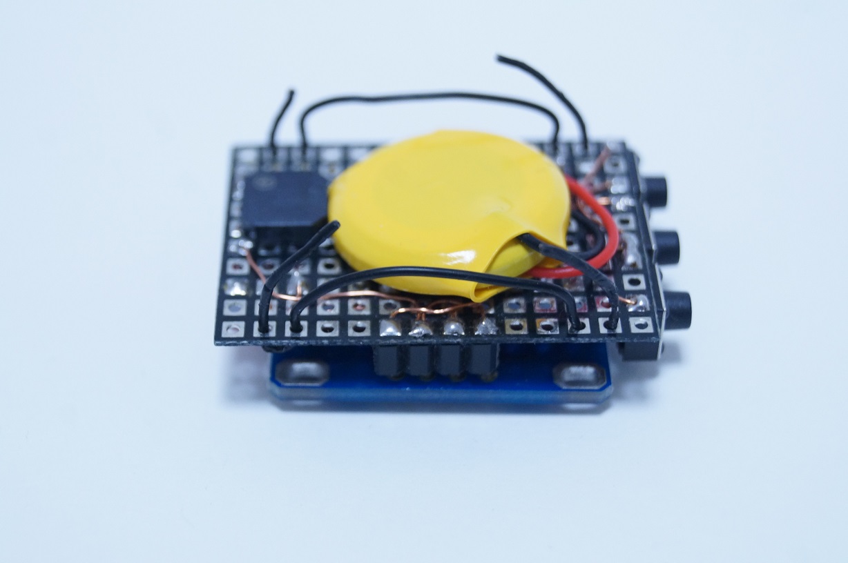
I chose a NATO strap for the watchband because it comes in a variety of widths and is easy for anyone to use. The strap shown the photo is 22mm wide. Refer to the photo to see how to secure the strap. You can use a thin wire to make a metal fitting and slip the watchband through and secure it.
I am a software engineer for web systems, but an amateur in terms of hardware development. I create electronic gadgets for fun.
The source code is available at GitHub. I look forward to your pull requests!
https://github.com/takjn

