
Title:Handmade 3D scanner using OpenCV
Displayed Name:@takjn
| Concept / Overview |
|---|
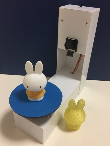
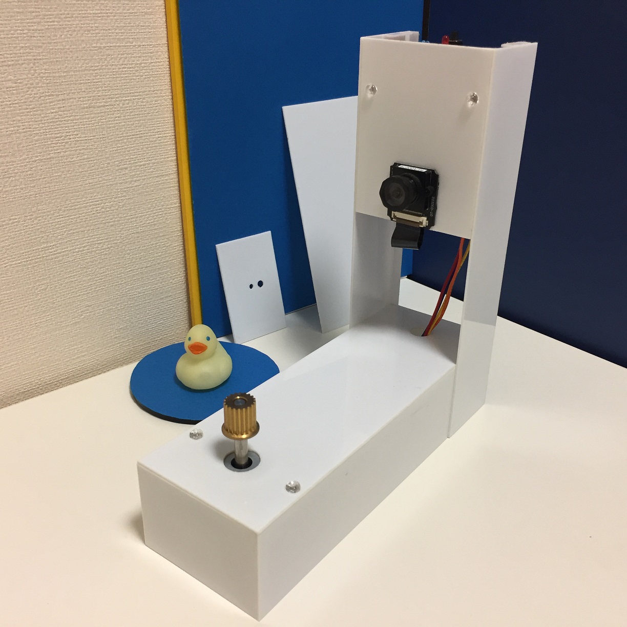
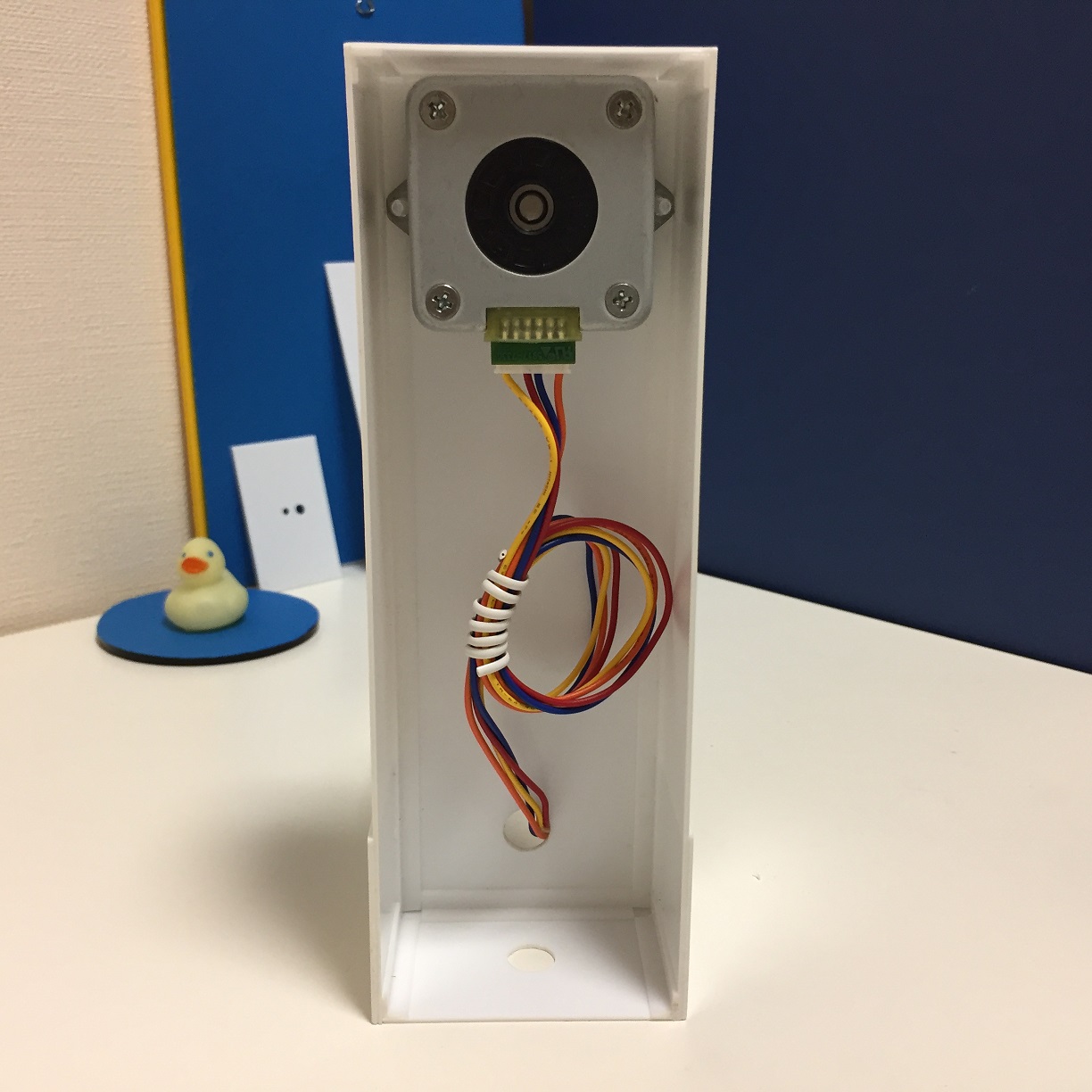
| I made a 3D scanner using the GR-LYCHEE camera and Open CV. You can make the same system with GR-PEACH. The system performs 3D-acquisition and saves the file with just the push of a button. The output file is an STL file, ready for use as is for a 3D printer. The above photo is of an actual item I made with a 3D printer from the 3D data by the scanner. Although the steps to make the scanner are rather complicated, this scanner can be made fairly easily with a minimum number of parts. Definitely give it a try! *I used the trial version (Rev.B) of GR-LYCHEE to make this system, and you might need some modifications when using the production version. |
Introduction
A 3D scanner is a machine for acquiring the shape of a target object as three-dimensional data. Commercial scanners usually employ sensors such as lasers, but this handmade scanner does not use a sensor at all; rather, it relies on images taken with the GR-LYCHEE or GR-PEACH camera and the OpenCV algorithm to acquire 3-dimensional data. If using GR-PEACH, camera calibration and other adjustments are necessary (see GR-PEACH details later in description.)
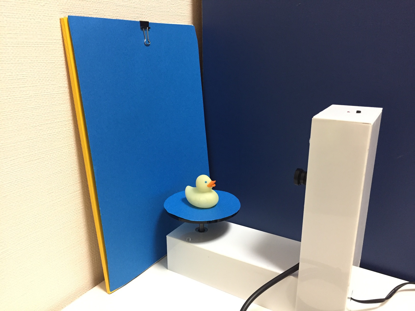
As this scanner utilizes a blue backdrop, it cannot correctly read the data of an object incorporating the color blue. Solid bright colors such as white or yellow facilitate reliable scanning. I created an object using children’s clay from a dollar store, and was able to scan it without difficulty.
This machine can scan 3-dimensional shapes with maximum dimensions (length, width, depth) of 100mm on each side. Due to the constraints of the algorithm, color cannot be read. The scanner cannot handle complex or irregular surfaces. For large or complex objects, try techniques such as scanning each section separately.
I have published the source code on GitHub. To modify the parameters or use GR-PEACH you will need to carry out a program build. To do so, prepare an online development environment in accordance with GR-LYCHEE online development procedure.
Algorithm (basic concept)
I used the “Shape from Silhouettes” algorithm to do the 3D-acquisition. This simply uses silhouettes (contours) of an object by taking multiple images with the camera. Reproducibility is less accurate when compared to methods like those using the image feature quantity, but Silhouette’s superiority lies in the ability to read 3D contours with relative speed and reliability. The concept of this method is shown below.
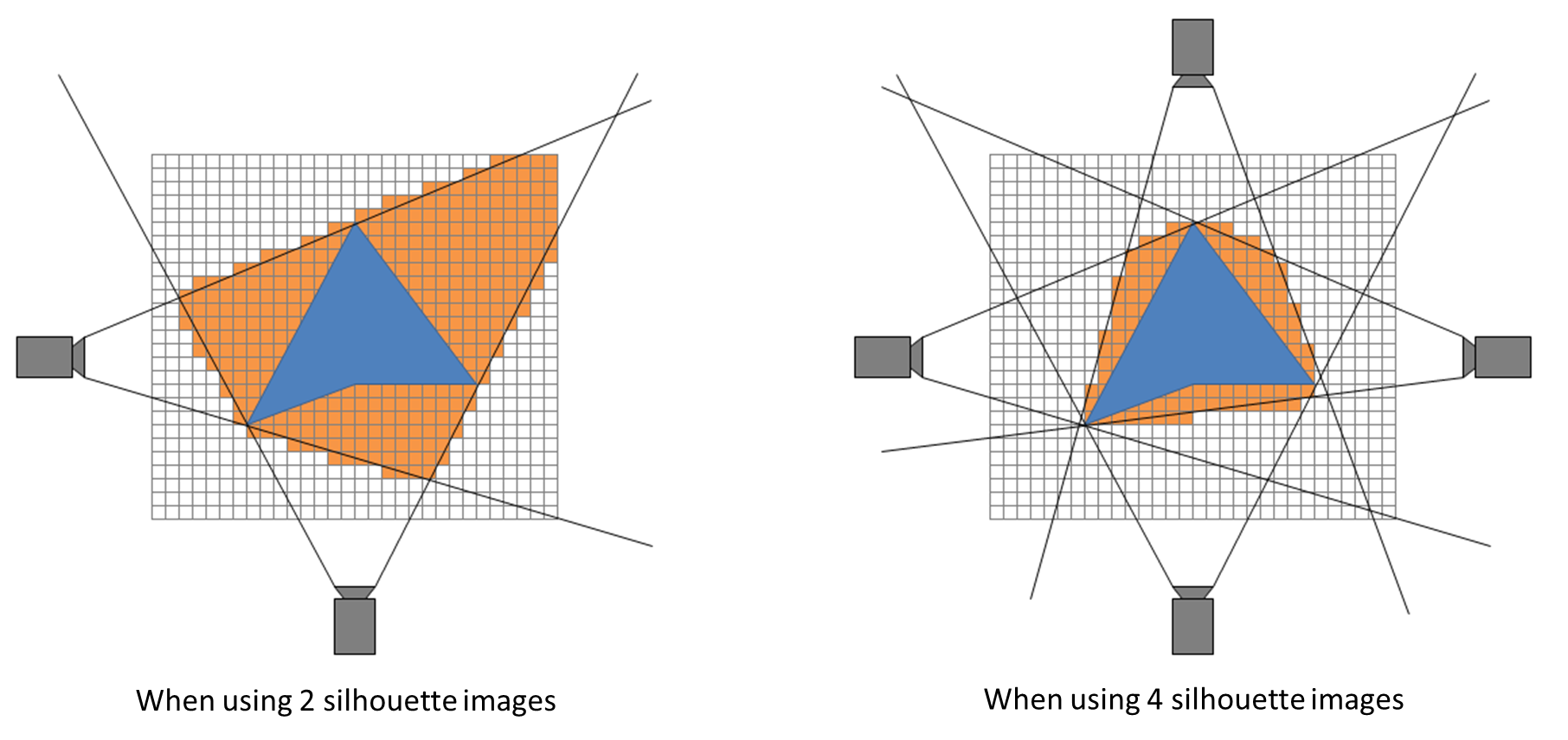
For objects with blue regions, the resulting black lines are the silhouettes (contours) captured by the camera, while the orange regions are the shapes estimated from the silhouette. As shown in the figure on the right (above), increasing the number of images taken from multiple viewpoints allows for a more accurate estimation of the object’s actual shape. This system uses a stepping motor to rotate the object, enabling images to be taken from multiple viewpoints.
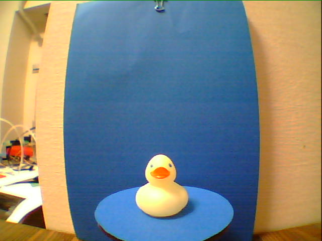
In order to capture the silhouette of an image with your camera, you must first remove the background. This project uses a process called “blue back” in which blue is the specified background color. I utilized OpenCV for this process. Sample images taken with this gadget are shown below. The image taken by the camera is on the left, the silhouette image is on the right. It appears that the image noise level is high, but “Shape from Silhouettes” is able to handle this level with no problem.

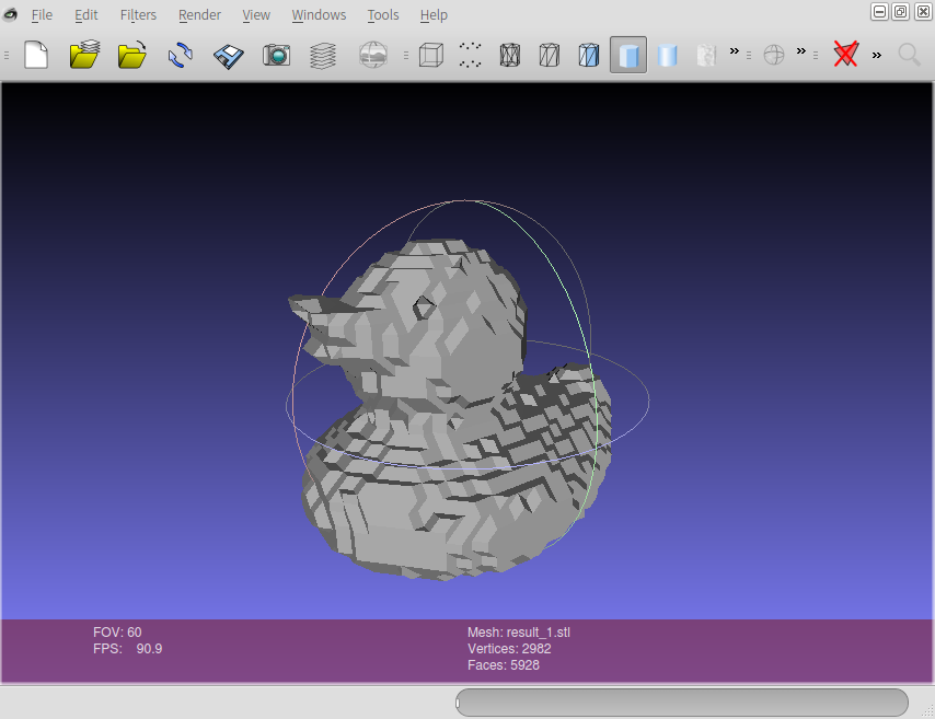
When the 3D scanning is completed, the data appears as Point Cloud Data, or an aggregate of dots representing the 3D object. To convert this to normal 3D data in order to use it with a 3D printer, we need to create a polygon mesh of the shape. I used a “Marching Cubes” algorithm library to generate the polygon mesh.
The following picture shows what the PC app reads, and displays the actual 3D data produced by the above silhouette image.
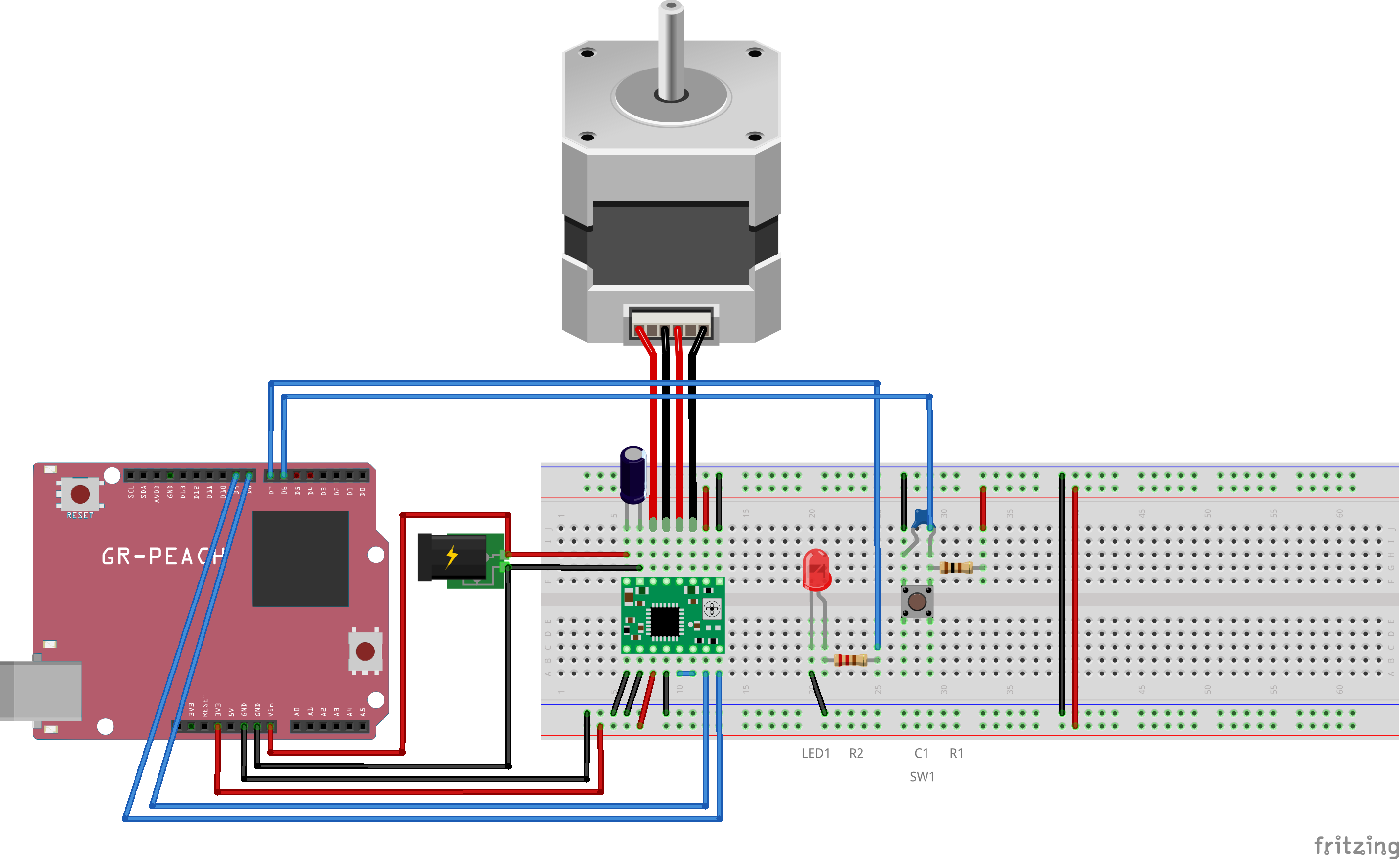
Circuit Diagram and Parts
List of componemts
| Name | # | Description |
|---|---|---|
| GR-LYCHEE or GR-PEACH | 1 |
GR-LYCHEE is scheduled for launch in November 2017. |
| Bipolar stepping motor | 1 | Choose a motor with a step angle of 1.8 degrees (200 steps total) and a 12V power. If you use a motor with differing specifications, you need to modify the program |
| Stepping motor driver A4988 | 1 | This is available from SwitchScience or amazon.co.jp, among other sources. As the circuitry for this project is configured with Quarter-Step, input 200 steps ÷ 1/4 = 800 steps yields to make the stepping motor rotate 360 degrees. |
| Tact switch (SW1) | 1 |
The switch is used as a start button. Press the switch to start the 3D-acquisition. |
| Resister 100Ω (R1) | 1 | |
| Ceramic capacitor 0.1μF (C1) | 1 | |
| Electrolytic capacitor 100μF (C2) | 1 | |
|
LED (LED1) |
1 |
This LED indicates the system is in an operation. The LED turns on during an SD card or USB memory being write-accessed. |
| LED resister 220Ω (R2) | 1 |
The resister value is a reference value; select the value in accordance with your LED. |
| DC jack | 1 | The DC jack is used to connect the 12V AC adapter. It should be purchased in accordance with the connector shape of the 12V AC adapter. |
|
Arduino-compatible universal shield or bread board |
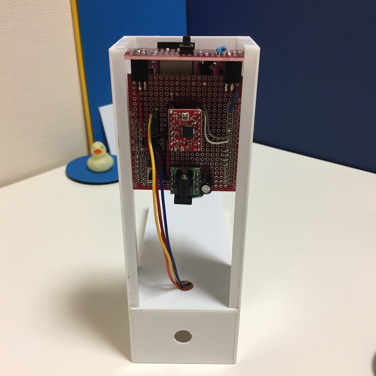
1 | In the photo shown at the beginning of this description, the components are mounted on the Arduino universal shield, but a bread board also works. |
| 12V AC Adapter | 1 | |
| Blue drawing paper | 2 |
The paper is used as both a camera backdrop and a turntable surface covering.
|
| Approx. 10cm small board | 1 | This will function as the turntable. This project used a round (8cm) acrylic-plate purchased which can be purchased in a hobby shop, but the board does not need to be round. A square board would work as well |
|
Tamiya PLA PLATE (1mm thickness) and plastic beams (5mm L-shaped type bar) |
- | This material is needed to make the housing, as shown in the first photo of this report. You will also need plastic adhesive. Thick paper or a universal plate (sold by Tamiya) can be used as alternative materials. |
| Strong double-sided tape | - | The tape is used for securing the camera to the housing and the turntable to the motor. |
| Screws, spacers, and fixing nuts | - | These items are used to secure the GR-LYCHEE and stepping motor to the main unit. |
Designing the housing
Dimension
The basic dimenion is shown below. Width and height should be adjusted according to the stepping motor size.
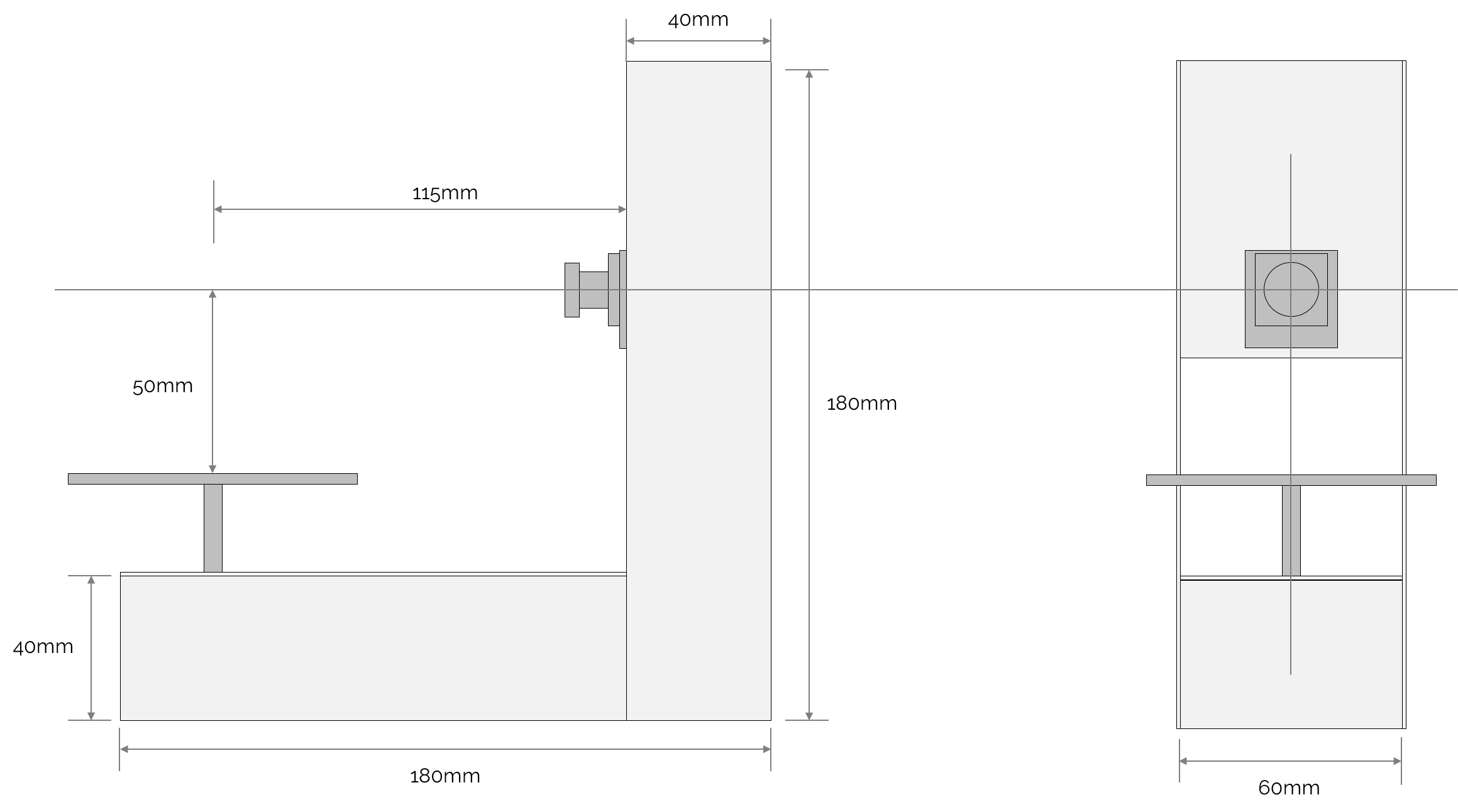
The height of the camera should be adjusted in accordance with the axle length of the stepping motor.
Theoretically, the point of intersection of the stepping motor’s rotation axis and the camera’s optical axis forms the base coordinates for the scanning process. The cubical space (100mm x 100mm x 100mm) 50mm from this center point toward the left/right, up/down, and back/front becomes the 3D acquisition space.
Accordingly, position the camera so that its central point rests 50mm above the turntable. If the position is off a bit, it can be adjusted in the program. But this makes the 3D acquisition space smaller, so the camera should be positioned in the center as accurately as possible.
Make sure the stepping motor’s rotation axis and the camera’s optical axis meet at a 90 degree angle.
Keep enough distance between the motor rotation axis and camera to obtain the proper 3D acquisition space. This distance also depends on the camera lens. In case of the GR-LYCHEE camera, the distance is 115mm or longer. If you want to change the distance, you need to adjust parameters in the program.
Supplement
To scan especially large objects you will need to change the housing and modify the program. You need to have a long distance between the camera and the motor rotation axis to gain a broad view. Modifying the program is simply a matter of adjusting parameters. But please note that the build-in memory is limited. For details on this, refer to the Troubleshooting section toward the end of this article.
Assembly
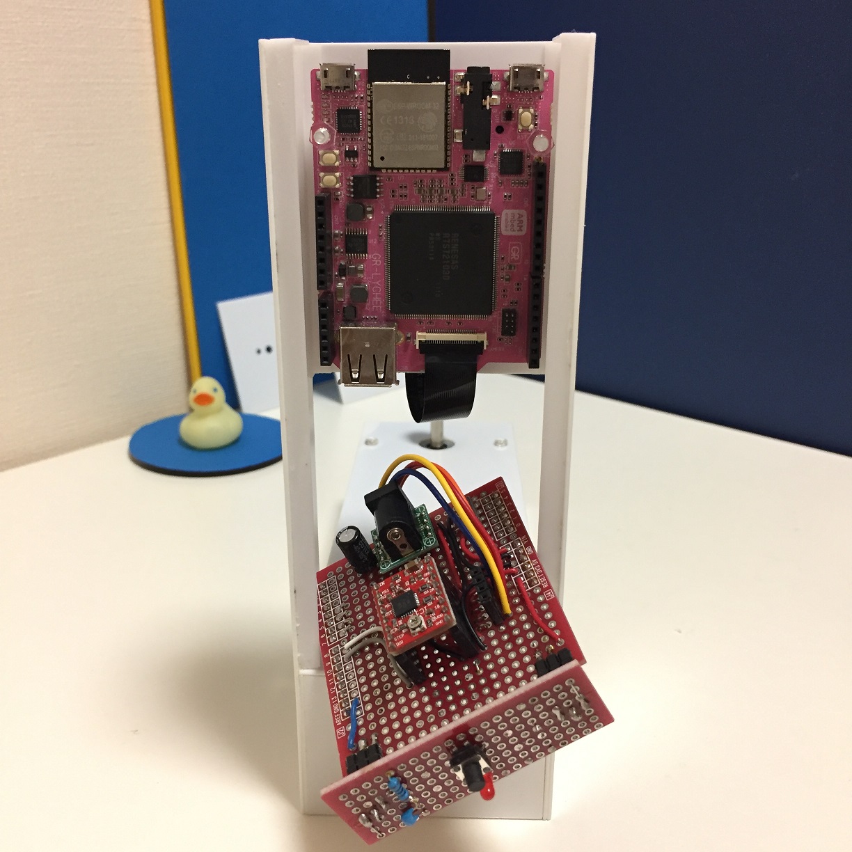
(1) Wiring on board
Wire the components on your board based on the above circuit diagram.
(2) Adjusting the stepping motor driver
After installation is completed, adjust the A4988 current to the rated current of the stepping motor. If the adjustment is not good, the stepping motor will not rotate smoothly due to insufficient current, or will overheat, which ends up damaging the motor or causing an accident. Use a tester for the adjustment. You will find a trimmer resister on the A4988 module to do the adjustment. For more details, refer to the manufacturer’s website.
After making adjustments, run the stepping motor to check the motor temperature. Be careful not burn yourself because the motor may be hot. When the adjustment is properly done, you won’t feel the system is hot even when it runs for a long time.
(3) Building the housing
I built the housing with Tamiya’s Pla Plate boards. Cut the board in accordance with the suggested dimensions and drill holes for securing the stepping motor and GR-LYCHEE, etc. Thereafter, use L-shaped sticks and adhesive to assemble the housing. To put the GR-LYCHEE and the motor on the housing, please use screws and spacers. To attach the camera on the housing, use a strong double-sided tape.
You should have no trouble scanning the object if the camera and stepping motor are aligned properly. However, to ensure greater scanning precision, assemble and align these two components accurately to have a perfectly vertical intersection of rotation axis and camera optical axis. If the camera is slanted or significantly out of place, the resulting scan will be distorted.
(4) Writing the program
For GR-LYCHEE, download the following program (build completed):
https://github.com/takjn/sfs4gr/raw/master/bin/sfs4gr.bin
Connect GR-LYCHEE to your PC, and write the downloaded program to the mounted MBED drive.
For GR-PEACH, or if you have altered the parameters, mbed import the following source code and then execute a build.
https://github.com/takjn/sfs4gr
Operation
(1) Connect the AC adapter to the 3D scanner.
Make sure the onboard LED is turned on (green with GR-LYCHEE, red with GR-PEACH), and the “processing” LED is off. If you see something abnormal, unplug the AC adapter and make sure there are no problems with the wiring.
(2) Put blue background papers in place, connect SD-card or USB memory to GR-LYCHEE.
You will be able to check the captured camera image using PC application (DisplayApp). Make sure the camera is properly focused and the background appears blue in the image. If it looks whitish or somewhat black due to the reflection of light, you will not be able to scan correctly. Try adjusting the lighting source.
(3) Place the object to be scanned on the turntable.
Use white or yellow clay to create an object to be scanned. If necessary, attach it to the turntable using double-sided tape to prevent it from moving. It is not critical for the object to be in the exact center of the turntable, but due the lens distortion, the farther the object is from the center of the turntable, the greater the likelihood of a distorted 3D scan.
(4) Press START button.
When you press the START button, the turntable will begin to rotate. Wait until it completes one full rotation. Confirm that the turntable is rotating to the left (counterclockwise). If it is not, refer to the Troubleshooting section toward the end of this article. The “processing” light will turn off once the process has been completed.
(5) Remove the SD card (or USB memory) and connect it to the PC.
The scan result is stored in file “result_1.stl”. Open it with the 3D builder included with Windows 10 or the 3D software bundled in the 3D printer. The mesh cloud data (before polygonization) is output at the same time as in the result_1.xyz file. You can achieve a better mesh operation using the 3D software called MeshLab.
The camera image files (*.jpg) are also stored in the memory device. If you are having trouble properly acquiring the object shape, you can check to see if the images were correctly photographed. For further details, check the following Troubleshooting section.
Troubleshooting
The turntable does not rotate when pressing the button.
Reset GR-LYCHEE or GR-PEACH. After resetting, make sure the onboard LED is on. If it is not on, check for wrong or bad wirings on the board. Check that the SD card or USB memory is also properly connected. Compatibility issues can also cause problems. If the access lamp does not turn off, try exchanging the memory device for another one.
Check to see if the AC adapter is properly connected. Also confirm that the AC adapter voltage and the stepping motor operating voltage are matched. Finally, see if the stepping motor driver is correctly adjusted.
The turntable is rotating, but the 3D data is not acquired.
Confirm that the turntable is rotating to the left (counterclockwise). If it is rotating to the right (clockwise), change the wiring of the stepping motor or adjust the program. (#define STEPPER_DIRECTION)
Confirm that the blue background paper is in place. Open the image file (*.jpg) and confirm that the background appears blue in the image and that the camera is focusing properly.
The bottom part of the acquired 3D image is cut off (or it includes unwanted images)
Try adjusting the position of the camera on the housing or modifying the program. (#define CAMERA_OFFSET)
The scanned image is distorted. Or part of the image is cut-off.
The camera is tilted, which may cause the image distortion or cut-off image. Additionally, if the stepping motor’s rotational axis and camera’s optical axis are not vertically intersecting, or if they are off center (the axis is not aligned), the scanned 3D image will be distorted. Check the camera is properly positioned. If the camera seems correctly positioned, following the suggestions in the Camera Calibration section.
To scan a larger object and/or acquire more detail.
If you adjust the PCD_SIZE and PCD_SCALE in tinypcl.hpp, you can acquire larger objects and/or more minute details.
PCD_SIZE x PCD_SCALE determines the 3D acquisition size (in mm). Due to the memory limitation of GR-LYCHEE, the maximum PCD_SIZE is 200. If you set PCD_SIZE to 200 and PCD_SCALE to 1, you can scan objects as large as 200mm x 200mm x 200mm.
If you wish to scan objects in finer detail, set the PCD_SIZE to 200 and the PCD_SCALE to 0.5. The scanned object is 100mm x 100 mm x 100mm, but the data will be acquired in 0.5mm grids.
Camera calibration
Scanning a 3D object requires internal parameters for the camera (optical center and focal length). These parameters in this system are set for the camera bundled with my GR-LYCHEE, but strictly speaking, parameters vary with each and every camera. I suggest your calibrate your camera and the parameters to improve scanning precision.
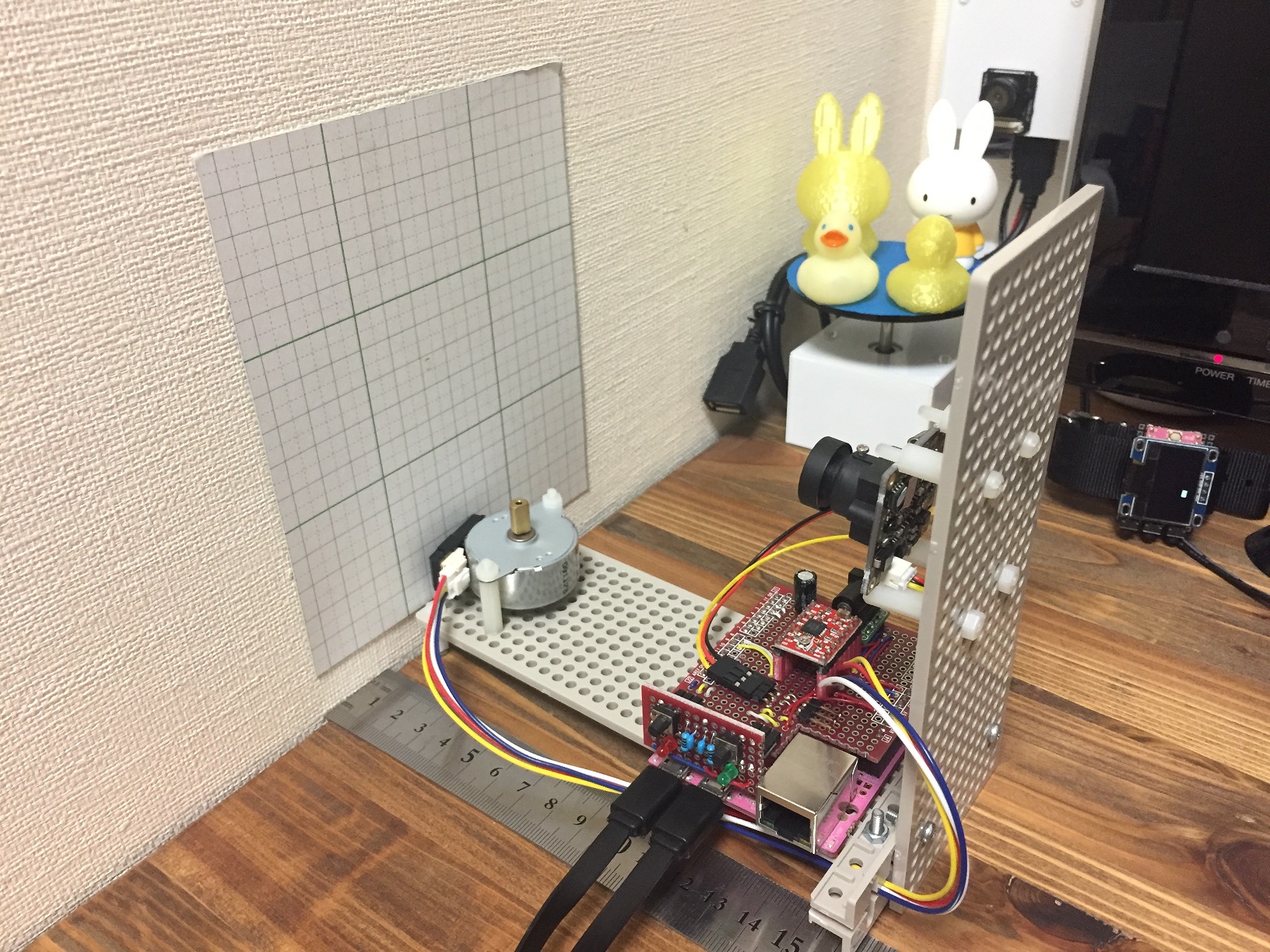
If the scanned image is distorted, try calibrating the camera as follows (see below). The photos and measurements shown below are scanned with an inexpensive (about 1,000 yen), 2.1mm wide-angle NTSC camera and GR-PEACH.
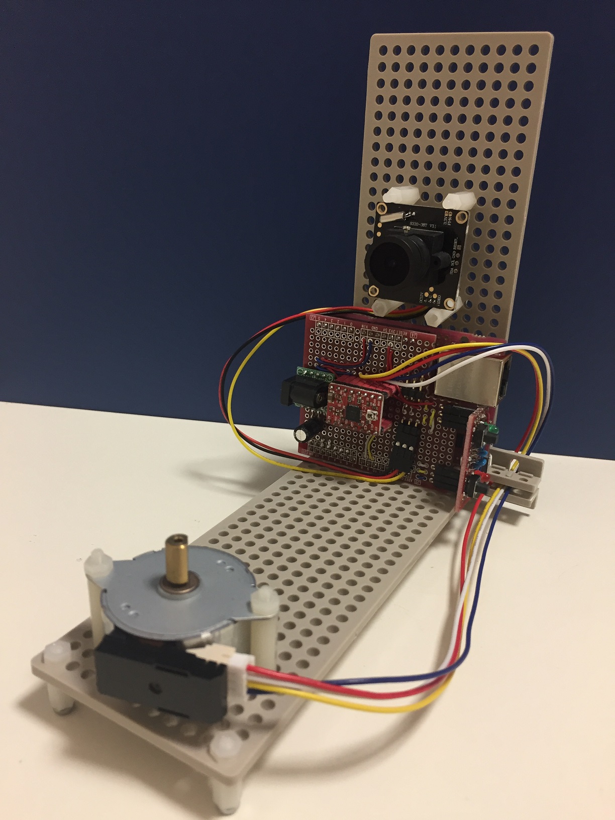
(1) Attach graph paper to a wall or vertical surface, and take a photo.
Set the camera and graph paper as shown in the photos below. Ensure that the camera is not tilted toward or away from the wall. And carefully measure the distance between the camera and the graph paper.
Connect an SD card or USB memory and press the START button, and save the photo. (As the background is not blue, this will take a bit longer than usual.)
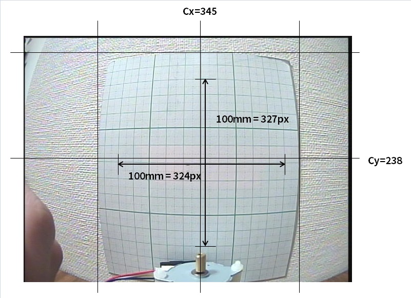
(2) Open the camera image saved in the memory device with editing software such as PAINT.
Check the optical center (Cx, Cy), referring to the example below. If you check the camera image, you will see that the grid is distorted and rounded. The optical center is located at the center of the distorted and rounded area. The image size is 640x480 pixels, so Cx will be around 320 pixels, and Cy around 240 pixels. Adjust the camera position so that rotation axis of the motor is on this optical center.
Next, measure pixel values that correspond to 100mm for both vertical and transverse directions. On the vertical side 100mm is 327 pixels, and on the transverse side 100mm is 324 pixels.
(3) Calculate the focal length.
Calculate the focal length of both the vertical side (Fy) and the transverse side (Fx). The distance between the graph paper and the camera measured in Step (1) is “L,” the transverse pixel count for 100mm measured in Step (2) is “Px,” and the vertical pixel count is “Py.” Fx and Fy should be as shown below.
• Fx = (Px / 100) * L
• Fy = (Py / 100) * L
(4) Set the obtained parameters in the source code and rebuild.
Set values Cx and Cy to camera internal parameters CAMERA_CENTER U and CAMERA_CENTER V in main.cpp. Set Fx and Fy to CAMERA_FX and CAMERA_FY.
Rebuild the source code and write it to the board.
Using GR-PEACH
This program has been confirmed to run on GR-PEACH. If you want to develop a system with GR-PEACH, please confirm the following instructions.
Housing and circuit diagram
There is no need to change the circuits. In terms of the housing, it may be necessary to change the distance between the camera and the stepping motor for the camera to view the entire 3D acquisition space, depending on your camera lens. Refer to a related article (see article here) to check the camera operations and image characteristics.
About the camera
I have already confirmed that an NTSC camera will work with this board. Connect the camera to the GR-PEACH NTSC-1A port. It is not necessary to use the GR-AUDIO + CAMERA board. However, please be sure to calibrate the camera as described above.
About the program
It is necessary to set the camera type. Rebuild your program after adding the following settings in section mbed_app.json:
"camera-type":{ "help": "Options are CAMERA_CVBS, CAMERA_MT9V111, CAMERA_OV7725", "value": "CAMERA_CVBS" },
I am a software engineer for web systems, but an amateur in terms of hardware development. I create electronic gadgets for fun.
The source code is available at GitHub. I look forward to your pull requests!
https://github.com/takjn
