
Title:GR Peach Based Smart Health Monitoring System with IoT
Displayed Name:Marwadi Education Foundation, RAJKOT
| Concept / Overview |
|---|
| Health care of elder people in India is very challenging problem. Currently the devices to measure heart rate, body temperature etc. are available as standalone consumer product. This project aims to design IoT based health monitoring system using GR-Peach development board of Renesas where elder patient's vital body parameters will be available to doctor as well as other family members via cloud services on Android application using MQTT Protocol. |
Objective
Proposed system will be useful for health monitoring of elder people as it provides remote monitoring facility of vital body parameters with cloud computing and analytics uses Amazon AWS Cloud services. Real time availability of heart rate, body temperature, SoS, Fall detection and Remote access of Real time ECG graph makes this system very useful in normal health monitoring as well as panic/emergency situations too. Aesthetics and proposed form
factor of chest strap will be easy to use by elder person. As all hardware and software details will be published in open source domain, anyone is having basic knowledge of embedded system can add more sensors/functionalities by considering this system as base development platform. Hands-on experience of Renesas MCUs and Android app development and Access of 3D-Printer will be proven very useful for execution of this project.
Main Objective of this project is to design open source Wearable Health monitoring Device for elder people using GR-PEACH Developemt Board from Renesas, which measures vital body parameters (i.e. Heart rate, ECG Graph, Body temperature (Fall Detection and Impact), SOS input and provide this information in real-time to user and doctor using Smartphone app via WiFi connection with cloud computing and analytics. Proposed system will be useful for other sensors as per real use scenario. Amazon AWS cloud service will be used for hosting MQTT broker and provide analytics in future. In perspective of Ditital India program, this project falls under Remote healthcare.
Design Methodology
Here is methodology used in implementation of proposed project. This system mainly consisting of hardware/firmware and android application,
1. Wearable Health Monitor Device
2. Android application for Family members and Doctor.
1. Wearable Health Monitor Device
As shown in fig.1 below, This module is battery powered WiFi enabled wearable GR
PEACH based device will be desig
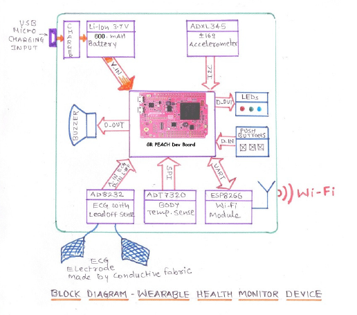
Fig.1. Block diagram Wearable Health monitor device
All sensors and modules integrated on a single add-on board to improve form factor and usability as wearable device.
My previous experience of designing IoT based wearable systems and android application development will play key role in execution of this project.
Durable enclosure for this device will be designed and fabricated with 3D-Printer.
Here are the details of different sensors and modules used in this wearable device.
a.Renesas GR-PEACH: This is heart of the entire device. R7S721001VCBG MCU on board will be used for interfacing different sensors and modules. All critical processing of real time sensor data will be done by GR-PEACH.
b.AD8232 ECG Sensor: AD8232 will be used in two electrode configuration to sense ECG signals. Leads off detection feature of AD8232 will be used to know those electrodes are correctly attached to chest or not. ECG Signal output of AD8232 is connected to GR-PEACH using ADC Input and heart rate will be processed by GR-PEACH. Leads off output of AD8232 are connected to Digital Input of GR-PEACH.
c.ADT7320 Temperature Sensor: ADT7320 is used for high precision body temperature sensing and it is interfaced with GR-PEACH using SPI Protocol.
d.ADXL345 Accelerometer ADXL345 +-16g Accelerometer is used for fall/impact detection. ADXL 345 will be interfaced with GR-PEACH using I2C Bus.
e.ESP8266 WiFi Module: All WiFi communication between Wearable health monitor device and android application running at user end or doctor end will be handled by ESP8266 module. ESP8266 will be interfaced with GR-PEACH using UART protocol. UDP communication over WiFi will be used to communicate with android application running at user end with WiFi Hotspot enabled on cell phone. ESP8266 will work as MQTT Client and subscribed to MQTT broker on internet to provide access of real time data to remote monitoring android application running at doctor end.
f.Li-Ion Battery: 3.7V 600mAH Li-Ion battery will be used for power up this device and proposed battery backup will be more than 36 hours.
g.Micro SD Card: All real time data with time stamp will be stored in SD Card. Network configurations like SSID and Password of preferred WiFi router/hotspot can be saved on SD Card for easy use of the device. On board dedicated SD Card connector on GR-PEACH will be used to interface micro SD Card with R7S721001VCBG using SPI Protocol.
h User LEDs and Push Buttons: LEDs will provide information of WiFi network status, SD card Status and other information to user. Push buttons will be used to provide user input to device like mode selections, restart, SoS etc.
j. Buzzer: Buzzer is used to provide audible feedback to user when certain body parameter crosses threshold level defined by user and also when Android app sends acknowledge of the SoS/Fall Detection and when module receives ECG graph request from Android App. It is connected to GR-PEACH on Digital Output.
2. Android application for User and Doctor:
Android application will be designed with Processing IDE for Android and it will be Open Source too, so any one can modify as per their requirements. Here are two possible use case for Android applications,
Use case 1: Personal health monitoring Android Application. User can monitor vital body parameter on his/her android cell phone using WiFi connection with wearable health monitor device.
Use case 2: Remote Health monitoring Android Application. This android application will be specially designed for doctor with real time data visualisation and alerts/ audio-visual notifications using cloud platform. fig.2 best describes android application and system use case.
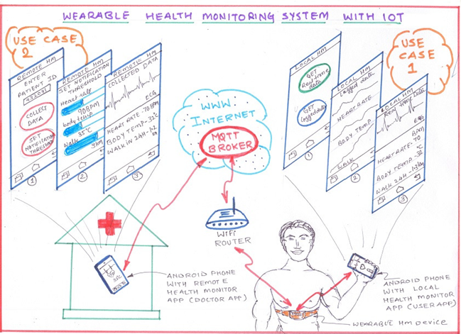
Fig.2. Use case of Android Application for Wearable health monitoring system
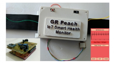
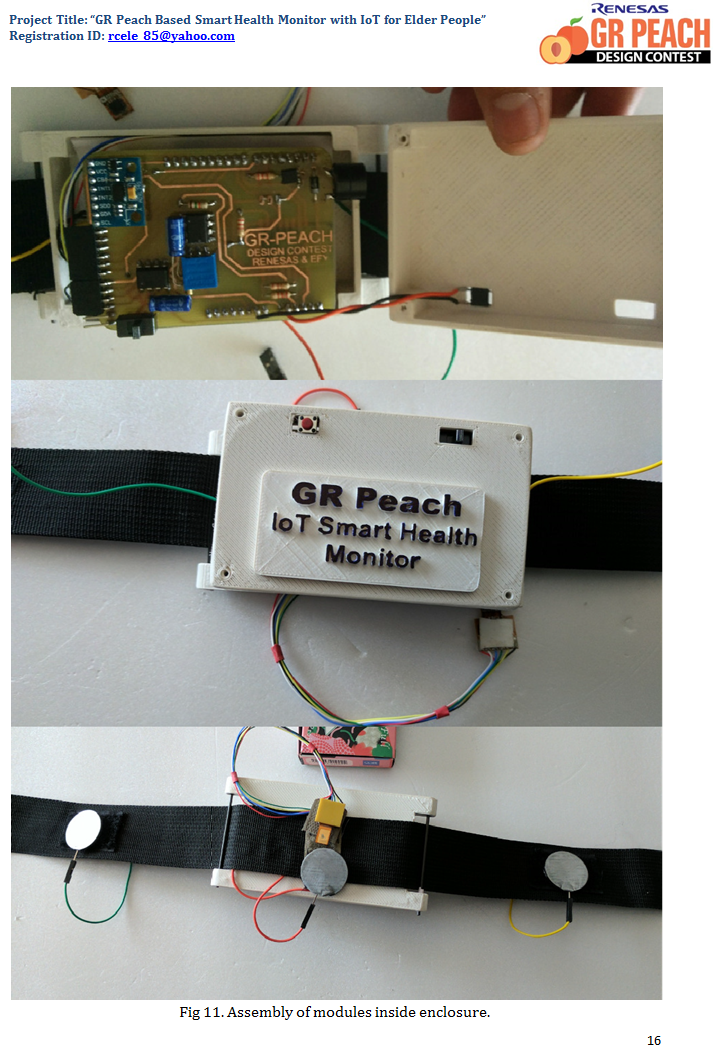
Final prototype will be design carefully considering aesthetics and ergonomics of real use case so it will be user friendly and perform all proposed operations gracefully. The enclosure of hardware will be designed using 3D-Printer and materials used for ECG electrode and other part of the system will be chosen as per user comfort. Fig.3 shows final prototype look and feel.
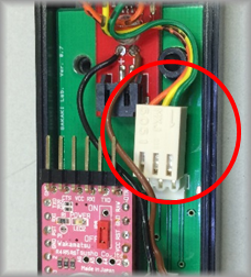
Fig.3. final prototype of Wearable health monitoring device
Project Implementation
We have considered elder people in mind while designing this project. All aesthetic focused in design of hardware, enclosure, chest strap and android application are as per end user requirements. In this chapter project implementation will be covered including schematic, BOM, PCB Layout, Android Application and Algorithms used in this project.
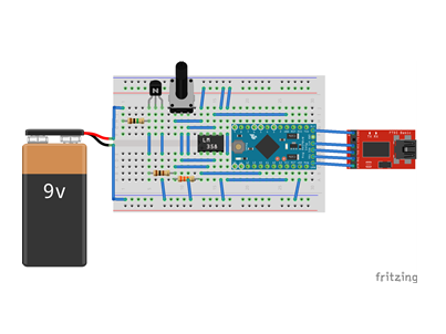
Following is connection Diagram in fig.4 self explains connections of various modules with GRPeach Shield and GR-PEACH Board.
Fig 4. Connection Diagram
GR-PEACH Board is connected to GRPeach SHM(Smart Health Monitor) Shield. ADT7320, AD8232, SOS/Config Button and MT3608 Boost regulator are connected with GRPeach SHM Shield. All modules including GR-PEACH Board are powered by 600 mAH LiIon Single cell Battery via MT3608 Boost regulator. Battery can be charged via USB micro connector on MT3608 module.
1: Renesas GR-PEACH: This is heart of the entire device. R7S721001VCBG MCU on board will be used for interfacing different sensors and modules. All critical processing of real time sensor data will be done by GR-PEACH.
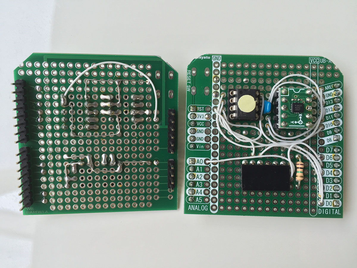
2: GRPeach SHM Shield: This header shield is designed for provide bridge between GR-PEACH Board and other sensor modules and it also have ESP8266 WiFi SoC for providing wireless internet connectivity to the module via WiFi. Following fig 5. and fig 6. are Schematic and pcb layout of this shield prepared in eagle and design files are hosted on google drive.
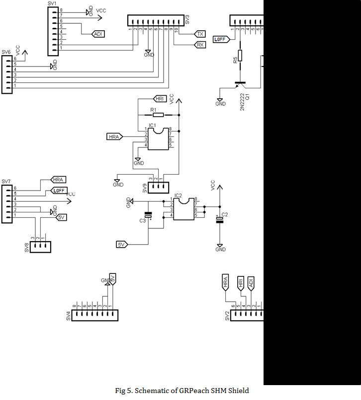
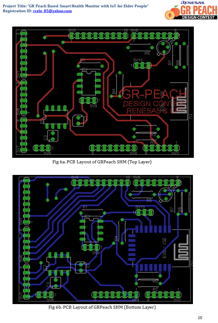
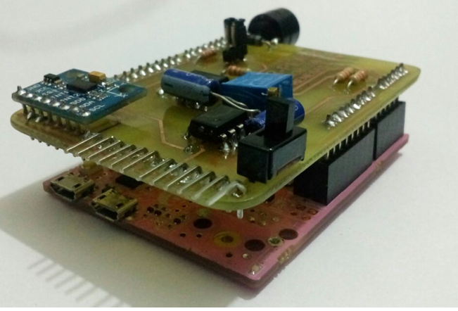
Fig 7c. Connection between GR-Peach and GRPeach SHM Shield.
GRPeach SHM Shield connected to following pins/Bus of GR-PEACH,
1.SPI Bus – for ADT7320 Temperature sensor Interfacing
2.I2C Bus – for ADXL345 Accelerometer Interfacing
3.Serial (UART) – for ESP8266 Interfacing
4.Analog Input – for AD8232 ECG signal interfacing
5.Digital Input/Interrupt – for AD8232 Leads off Signal, heart beat detected by TLV3402 Analog Comparator and SOS/Configuration button.
6.Digital Output – for Buzzer interfacing.
ECG Graph and Heart Rate: ECG signals collected from AD8232 are directly feed to analog input of GR-PEACH and will be used in case of send ECG Graph to remote android application. Here ECG analog signals are converted in digital at every 10ms for 400 samples. So 4 second ECG recording will be available on Android application.
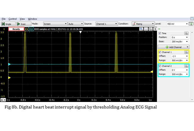
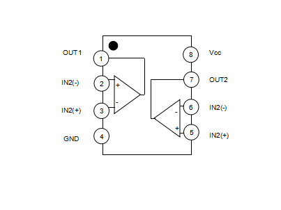
ECG analog signal also converted in digital by comparing it with threshold using TLV4302 comparator. And this digital signal feed to Interrupt In pin of GR-PEACH. By calculating time interval between two interrupt using timer library of mbed heart rate in BPM is measured. Measured heart rate is noisy due to motion artefacts of the human so min-max with running average algorithm is used for remove any motion artefacts from measured noisy heart rate and provide precise heart rate.
AD8232 leads off output is used to detect that ECG probes are touching skin of person or not hence to get to know that chest strap is wearied or not this leads off signal is used. Following fig 8a. and fig8b. self explains conversion of analog ECG signal to digital interrupt signal.
Fall Detection: ADXL345 8g 3axis accelerometer is used for detect human fall. ADXL345 is interfaced with GR-PEACH using I2C protocol. GR-PEACH collects all three axis acceleration samples at every 5ms and average them using moving average FiFo buffer. Than effective rms value of sum of all three axis is calculated. If effective rms value is less than 0.5g for duration of more than 400ms than it will be considered as fall. If fall is detected GR-PEACH send the notification to Android App vis ESP8266. and if no activity detected for 10 seconds after fall GR- PEACH consider it as a severe fall and send severe fall notification to the Android App. Here ticker library of mbed is used for take samples from ADXL345 at every 5ms so main loop is doing whatever function but sample never missed.
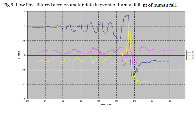
Fig 9. Low Pass filtered accelerometer data in event of human fall
ESP8266 WiFi SoC: ESP8266 WiFi SoC is interfaced on UART lines of GR-PEACH Board. We have modified the firmware of ESP8266 to support more custom commands for access configuration panel and MQTT connect, Publish and subscribe request initiated by GR-PEACH Board which is sent/received over UART at 9600 Baud Rate and encapsulated between ‘*’ and ‘#’ characters. The modified firmware binaries are hosted on google drive.
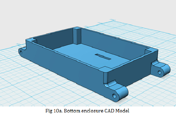
3D Printed Enclosure: Using Autodesk123d cool enclosure is designed for all electronic hardware parts on the chest strap. CAD Files and stl files for 3d print these enclosure parts are hosted on google drive. Following fig 10. Shows custom designed enclosure CAD Models.
Android Application: Android for remote monitoring of various vital health parameter is designed using Processing IDE with Android SDK. Apk file and Android application project files are hosted on google drive.
Following are the steps to initialize and use the GR-PEACH Smart Health Monitor Chest Strap Module.
1: Turn on the module and press SoS/Config button in 5 Seconds after power on to put chast strap in configuration mode. In configuration mode chest strap act as Access Point and host a web server so user can connect it using desktop/Laptop PC or cell phone browser having WiFi and configure Device ID, SSID and Password of proffered access point to which the chest strap module connects every time if not in configuration mode.
Following screen shots of android phone shows configuration steps.
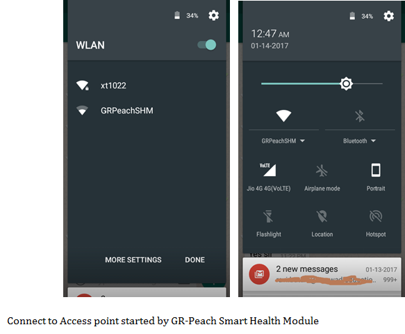
Sign In to the network open browser automatically with configuration panel of Chest Strap module. Select Configure WiFi option redirect to config panel.
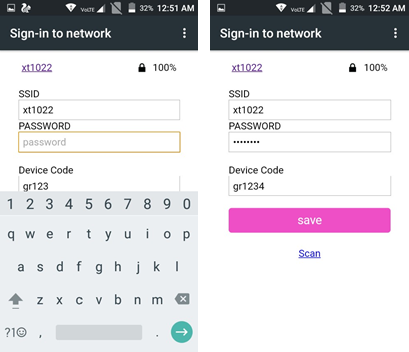
In config panel list of active access points will be scanned and listed automatically. Select one or if preferred access point is not broadcasting SSID than enter manually, enter password of preferred access point and finally enter unique device ID which will used in Android application to select which chest strap is going to connect with android app in multi user scenario. When save button selected, all configurations are saved in esp8266 for future connection after every power up cycle if SoS/Config button on chest strap is not pressed within 5 Seconds after power up. This video demonstration will be helpful to understand this process.
2: Remote Android App setup and use: After configuration done, every time module automatically connects to preferred access point and provide internet connectivity to GR- PEACH Board. Steady on blue LED in chest strap shows module is connected to network and blinking blue LED shows connection is not established with access poin .
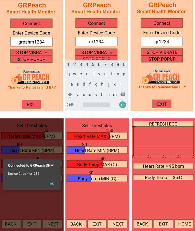
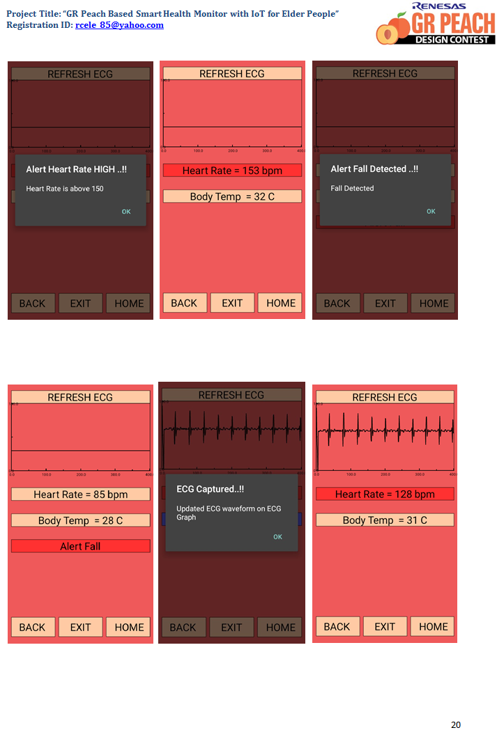
Following screen shots of my android phone self explains use of android application and this video demonstration shows chest strap module and android application in action.

Summary and future work
GR-Peach Based Smart Health Monitor with IoT is designed for elder people using GR- PEACH Board as heart of the project. It is wearable module in form of chest strap capable to measure heart rate, ECG Graph, body temperature, Fall detection with two level of severity and SoS/Panic notification button. The chest strap is having internet connectivity via WiFi using ESP8266 WiFi SoC. All communication between Android application and Chest Strap is done via internet using our custom designed MQTT broker hosted on Amazon AWS cloud service.
Future scopes is this project are to include Android push notification on event and design web server which provide health related data of multiple users at common website for future reference and data logging. We would also like to explore various low power modes of GR-PEACH R7S7 MCU to increase battery backup and would like to add wireless charging capability for battery as it is more convenient for elder people. We would also like to add SSL based MQTT Broker for secure connection between chest strap and android application. We would also like to reduce form factor of the chest strap by integrating all sensors, mcu and wifi soc on small PCB.
Firmware code of GR-Peach
We have used mbed online compiler IDE for GR-PEACH Programming in C++. Application Code of GR-PEACH Board, complete mbed project as a zip file is hosted on google drive and mbed developer website.
Here are the links.
Google Drive Link of GR-PEACH Code/binaries/mbed zip Project Mbed Developer Website GR-PEACH Project link for Import in mbed compiler
Code of main.cpp file just for reference is following, for compile the project please use bundled mbed project from google drive or import it in mbed compiler using above link.
Source
// GRPEACH SMART HEALTH MONITOR WITH IOT FOR ELDER PEOPLE
// Mbed Code for Renesas GR-PEACH REV-0
// Released Under Creative Commons Attribution-ShareAlike 3.0 Unported Licence

#include "mbed.h"
#include "ADT7320_SPI.h"
#include "math.h"
#include "ADXL345_I2C.h"

#define ESP_RXBUF_LEN 20

Serial pc(USBTX, USBRX); // tx, rx for USB Debug on PC
Serial esp(D9, D8);	// tx, rx for ESP8266 Interfacing on UART

ADT7320_SPI adt(D11, D12, D13, D10); // mosi, miso, sclk, cs for ADT7320 Temperature Sensor  Ticker acctick; // ticker for sample of adxl345 at every 10ms regardless what the loop doing

ADXL345_I2C accelerometer(I2C_SDA,I2C_SCL); // sda and scl for ADXL345 Temperature Sensor  Timer timer; // timer for measure time interval between two heart beat Interrupts

InterruptIn hr_int(P1_10);  DigitalOut buz(D6);  DigitalIn loff(D7);  DigitalIn sosconf(P1_9);  AnalogIn  ecg(P1_8);

volatile char esp_buf[ESP_RXBUF_LEN]; // Circular Buffer for ESP8266 Serial Receive As MODSERIAL not supported in GRPeach  volatile uint32_t  esp_pos = 0, esp_por = 0, esp_ok = 0, esp_head = 0; // Variable used for hold head and tail of Circular Buffer

volatile float ax,ay,az,a;  volatile float aavg = 50.0f;

uint32_t pre_millis=0;

uint32_t hr = 100,hrmax = 170,hrmin = 60,bt = 35,btmax = 40,btmin = 30,ecgreq = 0,flagack = 0, hf = 0,bf = 0,ff = 0,sf = 0;

// >>>>>>>>>>>>>>>>>>>>>>>>>>>>>>>>>>>>> ESP8266 UART Receive CallBack(ISR)
<<<<<<<<<<<<<<<<<<<<<<<<<<<<<<<<<<<<<<<<<<<<<<<<<<<<<<<<
void esp_callback() {
esp_buf[esp_pos] = esp.getc();  if(esp_buf[esp_pos]== '#')
{
esp_ok = 1;
}
esp_pos = (esp_pos+1)% ESP_RXBUF_LEN;
}

//>>>>>>>>>>>>>>>>>>>>>>>>>>>>>>>>>>>>> Beep on buzzer  <<<<<<<<<<<<<<<<<<<<<<<<<<<<<<<<<<<<<<<<<<<
void beep(unsigned int _beeps, float _on, float _off)
{
unsigned int _i;

for(_i=0 ; _i<= _beeps; _i++)
{
buz = 1;  wait(_on);  buz = 0;  wait(_off);

}

}

// >>>>>>>>>>>>>>>>>>>>>>>>>>>>>>>>>>>>> ADXL345 Ticker CallBack(ISR) to detect Impact
<<<<<<<<<<<<<<<<<<<<<<<<<<<<<<<<<<<<<<<<<<<<<<
void acctick_isr() {
int   accraw[3] = {0, 0, 0};
accelerometer.getOutput(accraw);  ax = (float)((int16_t)accraw[0])/5.2f ;  ay = (float)((int16_t)accraw[1])/5.2f ;  az = (float)((int16_t)accraw[2])/5.2f ;
a = sqrt(pow(ax,2.0f) + pow(ay,2.0f) + pow(az,2.0f));  aavg = aavg*0.85f + a*0.15f;
if(aavg < 30.0f)
{
beep(2, 0.3f, 0.3f);  ff = 1;
}
//printf("%3.1f%%\t%3.1f%%\r\n",aavg,a);

//printf("%d\t%d\t%d\r\n",accraw[0],accraw[1],accraw[2]);
}

// >>>>>>>>>>>>>>>>>>>>>>>>>>>>>>>>>>>>> ADXL435 Accelerometer Initlization  <<<<<<<<<<<<<<<<<<<<<<<<<<<<<<<<<<
void adxl345_init(void)
{
wait(.001);  accelerometer.getDeviceID();  wait(.001);
// These are here to test whether any of the initialization fails.  accelerometer.setPowerControl(0x00);
//Full resolution, +/-16g, 4mg/LSB.  wait(.001);  accelerometer.setDataFormatControl(0x0B);  wait(.001);
//3.2kHz data rate.
accelerometer.setDataRate(ADXL345_3200HZ);  wait(.001);
//Measurement mode.  accelerometer.setPowerControl(MeasurementMode);
}

// >>>>>>>>>>>>>>>>>>>>>>>>>>>>>>>>>>>>> ESP8266 UART returns how many chars available to read
<<<<<<<<<<<<<<<<<<<<<<<<<<<<<<<<<<<<<<<<<<<<<
int esp_available(void)
{
return ((ESP_RXBUF_LEN + esp_pos - esp_por) % ESP_RXBUF_LEN);
}

// >>>>>>>>>>>>>>>>>>>>>>>>>>>>>>>>>>>>> ESP8266 UART returns read one char
<<<<<<<<<<<<<<<<<<<<<<<<<<<<<<<<<<<<<<<<<<<<<<<<<<<<<<<<<<<<<<<<
char esp_read(void)
{
char c = esp_buf[esp_por];
esp_por = (esp_por + 1)% ESP_RXBUF_LEN;  return(c);
}

// >>>>>>>>>>>>>>>>>>>>>>>>>>>>>>>>>>>>> ESP8266 UART Flush receive Buffer
<<<<<<<<<<<<<<<<<<<<<<<<<<<<<<<<<<<<<<<<<<<<<<<<<<<<<<<<<<<<<<<<<
void esp_flush(void)
{
esp_pos = 0;
esp_por = 0;

}

// >>>>>>>>>>>>>>>>>>>>> ESP8266 UART returns comma seperated data points encapsulated between * and #
<<<<<<<<<<<<<<<<<<<<<<<<<<<<<<<<<<<<<<<<<<
int esp_read_cmd()
{
if (esp_ok == 1 )
{
char tmp[60];  char* temp;  esp_ok = false;  int _cnt = 0;
while(esp_read() != '*' );
tmp[_cnt] = esp_read();  while(tmp[_cnt] != '#')
{
_cnt++;
tmp[_cnt]= esp_read();
}
tmp[_cnt] = '\0';  esp.printf("%s\r\n",tmp);
temp = strtok(tmp, ",");  hrmax = atoi(temp);  temp = strtok(NULL, ",");  hrmin = atoi(temp);  temp = strtok(NULL, ",");  btmax = atoi(temp);  temp = strtok(NULL, ",");  btmin = atoi(temp);  temp = strtok(NULL, ",");  ecgreq = atoi(temp);  temp = strtok(NULL, ",");  flagack = atoi(temp);
pc.printf("%d %d %d %d %d %d\r\n",hrmax,hrmin,btmax,btmin,ecgreq,flagack);  return 1;
}
else return 0;
}

//>>>>>>>>>>>>>>>>>>>>>>>>>>>>>>>>>>>>> ECG/HR ISR  <<<<<<<<<<<<<<<<<<<<<<<<<<<<<<<<<<<<<<<<<<<
void hr_isr()
{
uint32_t _hr;
_hr = timer.read_ms() - pre_millis;  pre_millis = timer.read_ms();
//pc.printf("premillis  = %d ",pre_millis);
_hr = 60000/_hr;
if(_hr > 31 && _hr < 200)
{
hr = ((hr*14) + _hr)/15;
}
if(loff == 1)hr=31;  if(hr <= hrmin)hf = 1;
else if(hr >= hrmax)hf = 2;  else hf = 0;
//pc.printf("Heart Rate = %d \r\n",hr);
}

//>>>>>>>>>>>>>>>>>>>>>>>>>>>>>>>>>>>>> ECG capture Graph and send to ESP8266  <<<<<<<<<<<<<<<<<<<<<<<<<<<<<<<<<<<<<<<<<<<
void esp_send_ecg(void)
{
uint32_t _cnt = 0;  beep(4,0.2f,0.5f);
wait(2.0f);  beep(1,0.2f,0.1f);
for(_cnt=0; _cnt<410; _cnt++)
{
float raw = ecg.read();
uint32_t ecg_point = (uint32_t)(((raw*100.0f)-13.15f)*1.66f);  if(ecg_point > 99)ecg_point=99;
esp.printf("%d,",ecg_point);  pc.printf("%d,",ecg_point);

wait(0.01f);
}
esp.printf("10#");  pc.printf("10#\r\n");
pc.printf("ecg graph packet sent..\r\n");  beep(1,0.9f,0.1f);
}

//>>>>>>>>>>>>>>>>>>>>>>>>>>>>>>>>>>>>> ECG capture Graph and send to ESP8266  <<<<<<<<<<<<<<<<<<<<<<<<<<<<<<<<<<<<<<<<<<<
void esp_send_data(void)
{
esp.printf("*%d,%d,%d,%d,%d,%d,%d,%d,%d,%d#",hr,hrmax,hrmin,bt,btmax,btmin,hf,bf,ff,sf);  pc.printf("*%d,%d,%d,%d,%d,%d,%d,%d,%d,%d#\r\rn",hr,hrmax,hrmin,bt,btmax,btmin,hf,bf,ff,sf);
pc.printf("data packet sent..\r\n");
}

//>>>>>>>>>>>>>>>>>>>>>>>>>>>>>>>>>>>>> Read ADT7320 Temperature sensor & bf flag  <<<<<<<<<<<<<<<<<<<<<<<<<<<<<<<<<<<<<<<<<<<
void read_adt_temp(void)
{
bt = (uint32_t)(adt.readTemp());  if(bt <= btmin)bf = 1;
else if(bf >= btmax)bf = 2;  else bf = 0;
}

//***************************************** MAIN FUNCTION *******************************************  int main() {
uint32_t loop_cnt = 0;  wait(0.2f);
pc.baud(9600);  esp.baud(9600);  esp.attach(&esp_callback);  adxl345_init();
wait(0.01f);
acctick.attach(&acctick_isr, 0.02);  timer.start();
hr_int.rise(&hr_isr);  buz = 0;
for (int ap=0; ap<=50; ap++)
{
if(sosconf == 0) beep(1,1.0f,0.2f);  wait(0.1f);
}
// Do forever.  while(1)
{
esp_read_cmd();
read_adt_temp();  if(ecgreq == 1)
{
esp_send_ecg();  ecgreq = 0;
}

if(loop_cnt >= 50)
{
esp_send_data();  loop_cnt = 0;
}
if(flagack == 1)
{
beep(3,0.4f,0.4f);  flagack = 0;
sf = 0;  ff=0;  hf=0;  bf=0;
}
loop_cnt++;  wait(0.1f);
}
}
Android Application
We have used Processing IDE with Android SDK for Android Application Development of GR- Peach based Smart Health Monitor module.
Apk file for direct installation of android application on android cell phone and complete sketch book of processing for modify the android application is hosted on google drive with following link.
Google Drive Link for Android Application APK file and Processing Android project
There is no meaning of pasting the code of android application with more than 2000 lines so I request you to import the same from google drive as a reference.
Demo Video
References
http://cecs.wright.edu/atrc/wearable-portable%20health%20monitoring%20system.html
https://www.wearable-technologies.com/2015/04/wearables-in-healthcare/ http://ieeexplore.ieee.org/xpls/abs_all.jsp?arnumber=5306098 http://link.springer.com/chapter/10.1007/978-3-642-39476-8_36
http://www.nxp.com/assets/documents/data/en/reference-manuals/MMA7260QHFDRM.pdf
https://developer.mbed.org/platforms/Renesas-GR-PEACH/
mbed Project Link
https://developer.mbed.org/users/rcele_85/code/GRPEACH_SHM_FINAL/
Google Drive link for all docs/codes/design files
https://drive.google.com/drive/folders/0B720xXRyaIq8cVBQRVVaY2NoZnM?usp=sharing
Luchy winner for timely submittoin & technical merit